39
English
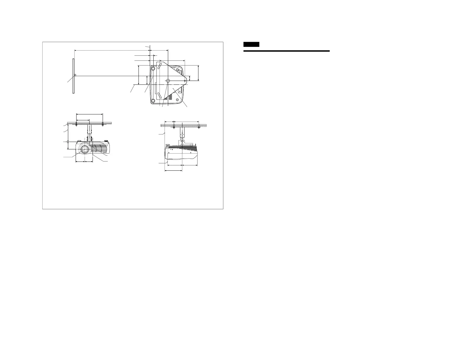
Attaching the projector suspension
support PSS-610
For more details on the ceiling installation, refer to the
Installation manual for Dealers of the PSS-610. The
installation measurements are shown on page 38 when you
install the projector on the ceiling.
Top view C
Align the center of the lens with the center of the screen.
Front view D
The lens is offset 43.4 mm (1
3
/
4
inches) to the left from the
center of the supporting pole. When mounting, take care to
align the center of the lens with the center of the screen; not
the center of the supporting pole.
Side view E
a : distance between the screen and the center of the lens
1 Center of the screen
2 Center of the unit
3 Front of the cabinet
4 Upper ceiling mount bracket
5 Center of the supporting pole (The center of the
supporting pole is different from that of the unit.)
6 Center of the lens
7 Ceiling
8 The bottom surface of the mounting bracket
9 Distance between the ceiling and the surface of the
mounting bracket
Using adjustment pipe (b): 150/175/200 mm
(6/7/7
7
/
8
inches)
Using adjustment pipe (c): 250/275/300 mm
(9
7
/
8
/10
7
/
8
/11
7
/
8
inches)
0 Front of the lens