INDEX Page. 9 of 92
1. PANEL DESCRIPTION
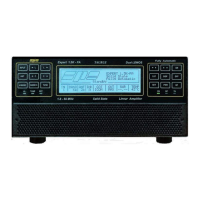
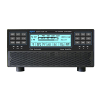
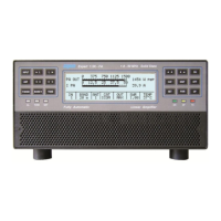
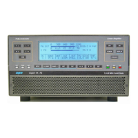
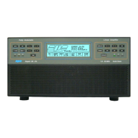
1.1 Front Panel
1) ON turns on unit.
2) OFF turns off unit when held down for three seconds.
3) DISPLAY toggles between display pages.
4) POWER switches output power between “MAX / MID / LOW“
5) OP toggles back and forth between Standby/Operate modes.
6) SET used to program the amplifier.
7) ▼► used to program the amplifier.
8) ◄▲ used to program the amplifier.
9) INPUT selects one of the two inputs of the amplifier.
10) ◄BAND switches bands manually (downward in frequency).
11) BAND► switches bands manually (upward in frequency).
12) ANT switches the antennas when programmed for use.
13) CAT shows the current CAT interface setting.
14) TUNE: starts the automatic tuning process.
15) ◄C used for manual tuning.
16) C► used for manual tuning.
17) ◄L used for manual tuning.
18) L► used for manual tuning.
19) TX red LED, illuminates during transmission.
20) OP yellow LED, illuminates when the amplifier is in “Operate” state.
21) ON green LED, illuminates when the amplifier is “ON”.
22) SET green LED, illuminates during programming.
23) TUNE yellow LED, illuminates during tuning.
24) AL red LED, illuminates when there is an alarm.
25) LCD DISPLAY
26) AIR-FILTER GRID
Note: Pressing [CAT] key two times, will show the current firmware version.