| Description | 10
Camera Link Camera External Interfaces
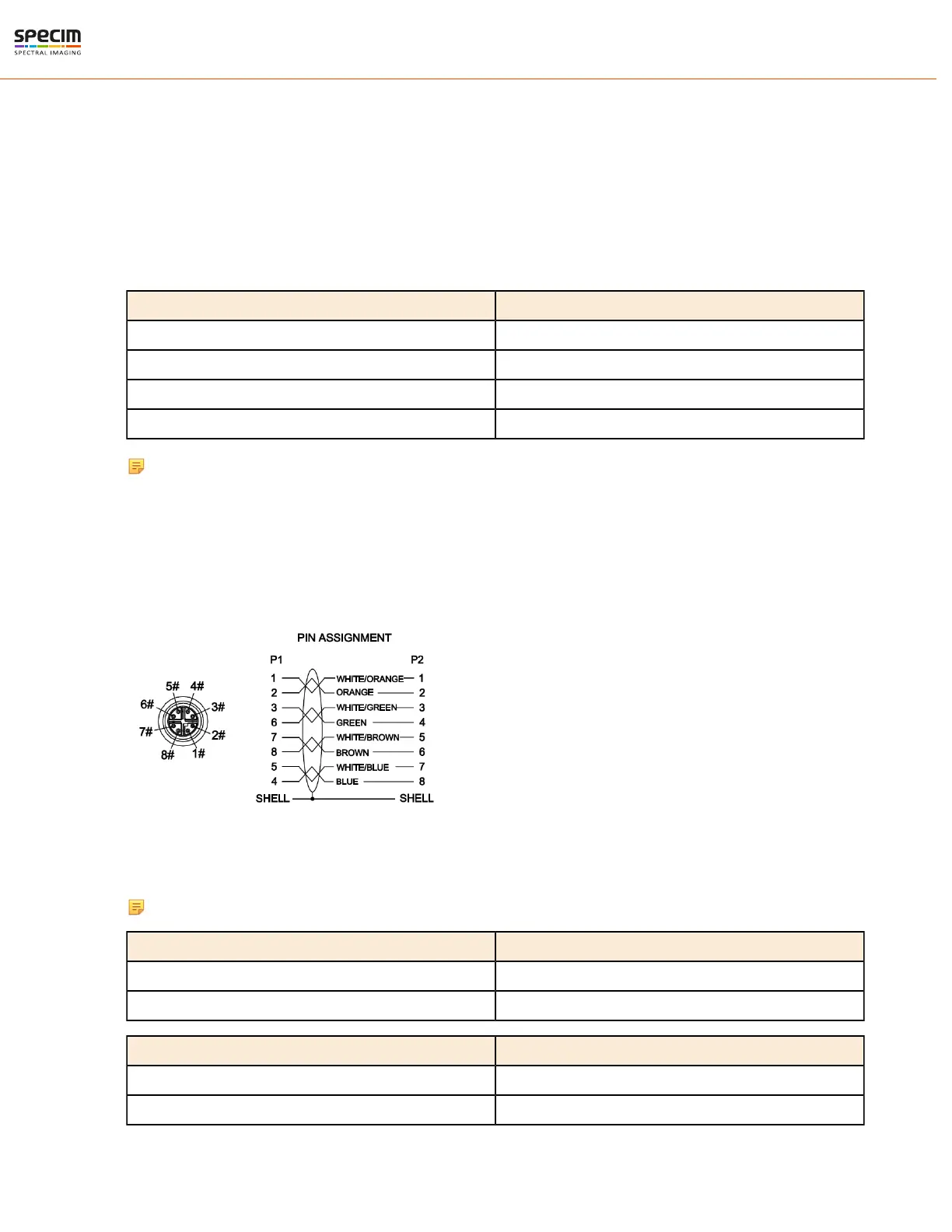
Camera Link Connector
There is a standard MDR 26-pin camera link connector on the back panel of the camera for camera control signals
and serial communication.
For more information on Camera Link connector, refer to Camera Link interface standard specifications.
LED Indications
There is one green LED in the FX camera back panel.
LED Status
Not lit Power off
Blinking green in startup Starting up
Stable green Power on, not recording
Blinking green Recording, data being transferred
Note: Camera blinks briefly during startup. This period can be very short and therefore easy to miss.
GigE Camera External Interfaces
GigE Connector
There is a standard GigE M12 X-coded Ethernet connector on the back panel of the camera for camera control signals
and serial communication.
LED Indications
There are three green LEDs in the FX camera back panel, one for status and two for GigE traffic indication.
Note: The LED light may appear dim.
Status LED Status
Not lit Power off
Stable green Power on
GigE LED 1 Status
Not lit No data connection
Blinking green Data connection active
All rights reserved - Specim, Spectral Imaging Oy Ltd.
 Loading...