| Description | 9
All the corrections are enabled by default.
Regions of interest
The image sensor in FX series cameras is larger than the actual image size. Therefore the image area on the sensor
is defined using the Region of Interest (ROI) feature, and the ROI values are provided in the calibration pack. ROI
feature is reserved for this purpose alone, and the values must not be changed.
You can use Multiple Regions of Interest (MROI) feature to define one or several regions of interest. Using MROI
feature requires 1 x 1 binning.
If you use AIE together with MROI, there must be additional 3 rows in the beginning and in the end of each MROI to
prevent corruption. These extra rows must then be discarded in data processing as their data may be invalid.
External Interfaces
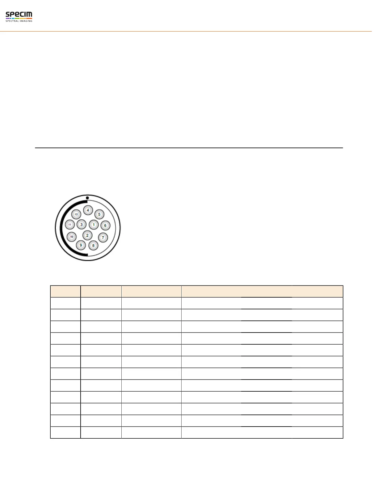
Power Connector
There is one Fischer Connector DBPLU1031Z012|130G in the camera back panel.
Power Connector Pin numbering
Table 1: Power Connector Pin-out
pin # I/O Type Name Description
1 O ISO_OUT0 General purpose Output 0, single-ended output
2 O ISO_STROBE Default Strobe out, single-ended output
3 O RESERVED Reserved, do not connect
4 PWR CAMERA_GND Camera GND, 0V
5 PWR CAMERA_PWR Camera Power 12V (+/- 10%), no polarity protection
6 PWR ISO_GND I/O GND, 0V
7 I ISO_IN0 General purpose input 0 (5 V)
8 I ISO_TRIGGER Default Trigger in (5-15 V)
9 O RESERVED Reserved, do not connect
10 O RESERVED Reserved, do not connect
11 O RESERVED Reserved, do not connect
12 O RESERVED Reserved, do not connect
All rights reserved - Specim, Spectral Imaging Oy Ltd.
 Loading...