| Functionality | 30
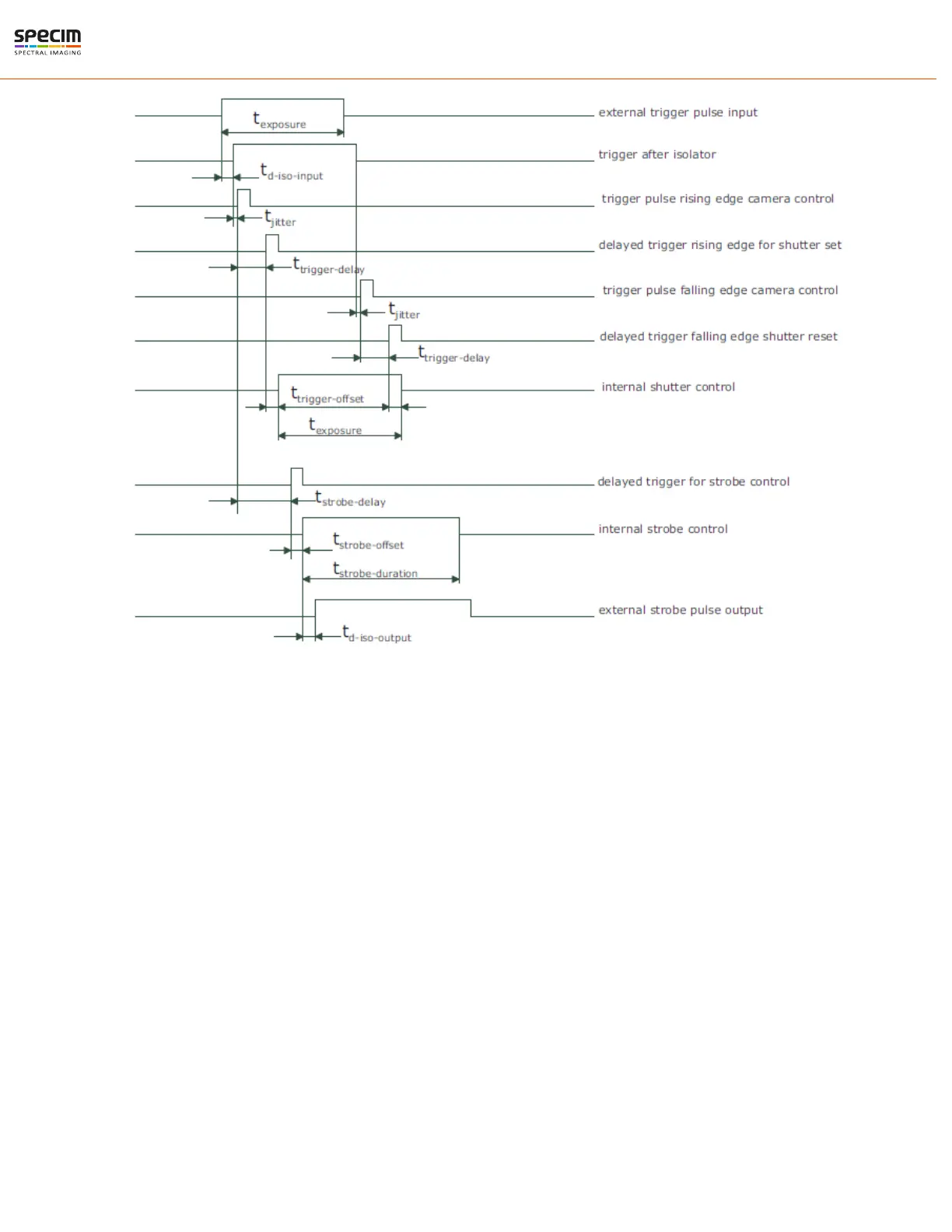
Figure 28: Timing diagram for the pulse width controlled exposure time
The timing of the rising edge of the trigger pulse until to the start of exposure and strobe is equal to the timing of the
camera controlled exposure time. In this mode, however, the end of the exposure is controlled by the falling edge of
the trigger pulse width: The falling edge of the trigger pulse is delayed by the time t
d−iso−input
which is results from the
signal isolator. This signal is clocked into the FPGA which leads to a jitter of t
jitter
. The pulse is then delayed by t
trigger
−delay
by the user defined value which can be configured via camera software. After the trigger offset time t
trigger−offset
the exposure is stopped.
Trigger delay
The trigger delay is a programmable delay in milliseconds between the incoming trigger edge and the start of the
exposure. This feature may be required to synchronize to external strobe with the exposure of the camera.
Burst trigger
The camera includes a burst trigger engine. When enabled, it starts a predefined number of acquisitions after one
single trigger pulse. The time between two acquisitions and the number of acquisitions can be configured by a user
defined value via the camera software. The burst trigger feature works only in the mode "Camera controlled Exposure
Time".
All rights reserved - Specim, Spectral Imaging Oy Ltd.
 Loading...