| Functionality | 38
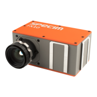
Figure 33: LFSR test pattern received at the frame grabber and typical histogram for error-free data
transmission
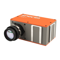
Figure 34: LFSR test pattern received at the frame grabber and histogram containing transmission
errors
Note: A possible origin of failure message can be caused by the Camera Link cable which exceeds the
maximum length. Also, Camera Link cables may suffer either from stress due to wrong installation or from
severe electromagnetic interference.
Note: Some thinner Camera Link cables have a predefined direction. In these cables not all twisted pairs are
separately shielded to meet the RS644 standard. These pairs are used for the transmission of the RX/TX and
for the CC1 to CC4 low frequency control signals
Note: Camera Link cables contain wire pairs, which are twisted in such a way that the cable impedance
matches with the LVDS driver and receiver impedance. Excess stress on the cable results in transmission
errors which causes distorted images. Therefore, please do not stretch and bend a Camera Link cable.
In robots applications, the stress that is applied to the Camera Link cable is especially high due to the fast movement
of the robot arm. For such applications, special drag chain capable cables are available. Contact Specim for more
information.
All rights reserved - Specim, Spectral Imaging Oy Ltd.
 Loading...