| Configuration Options | 40
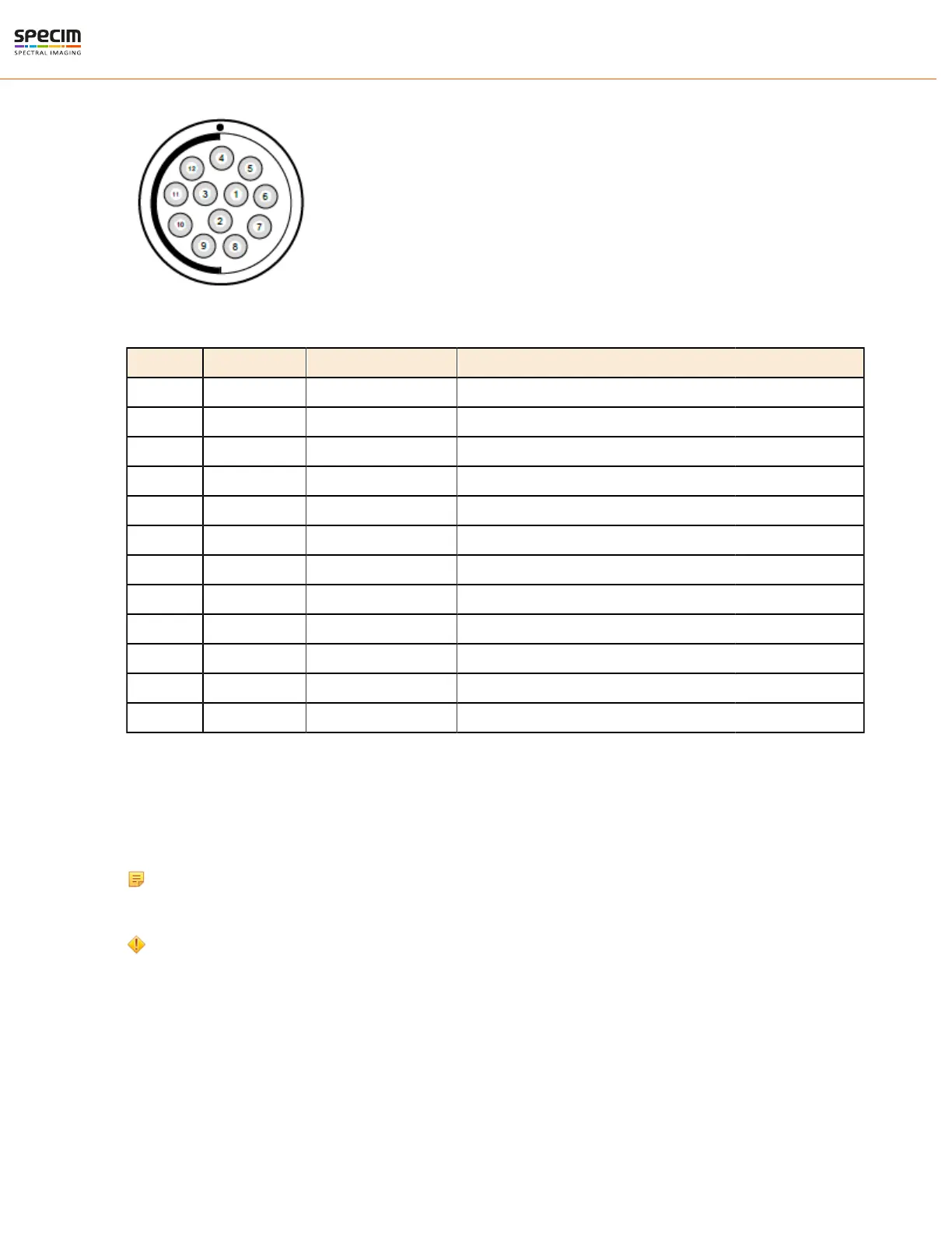
Pinout
Table 7: Power Connector Pin-out
pin # I/O Type Name Description
1 O ISO_OUT0 General purpose Output 0, single-ended output
2 O ISO_STROBE Default Strobe out, single-ended output
3 O RESERVED Reserved, do not connect
4 PWR CAMERA_GND Camera GND, 0V
5 PWR CAMERA_PWR Camera Power 12V (+/- 10%)
6 PWR ISO_GND I/O GND, 0V
7 I ISO_IN0 General purpose input 0 (5 V)
8 I ISO_TRIGGER Default Trigger in (5-15 V)
9 O RESERVED Reserved, do not connect
10 O RESERVED Reserved, do not connect
11 O RESERVED Reserved, do not connect
12 O RESERVED Reserved, do not connect
Trigger input
The Trigger Input on FX Series cameras is opto-isolated. Trigger Input is pin #8 ISO_TRIGGER. Use pin #6
ISO_GND as a ground signal. Trigger signal input range is with 5 to 15 VDC. Acceptable minimum Trigger Input
pulse width is 0.2 us. Maximum pulse width is half of frame period. For example, with 100 fps the half would be 5
ms.
Note: The trigger input is equipped with a constant current diode which limits the current of the optocoupler
over a wide range of voltage. Trigger signals can thus directly get connected with the input pin and there is no
need for a current limiting resistor, that depends with its value on the input voltage.
Caution: The input voltage to the ISO_TRIGGER pin must not exceed +15V DC, to avoid damage to the
internal ESD protection and the optocoupler!
Strobe Output
The Strobe Output is pin #2 ISO_STROBE. Use pin #6 ISO_GND as a ground signal. To use the Strobe Output, the
internal optocoupler must be powered with 5 to 15 VDC (STROBE_VDD). The ISO_STROBE signal is an open
collector output; therefore, the user must connect a pull-up resistor of e.g. 1 kΩ to STROBE_VDD. STROBE_VDD
must be supplied by the user. This resistor should be located directly at the signal receiver. Acceptable minimum
Strobe Output pulse width is 0.2 us. Maximum pulse width is half of frame period. For example, with 100 fps the half
would be 5 ms.
All rights reserved - Specim, Spectral Imaging Oy Ltd.
 Loading...