SS1000 Operator’s Manual v
LIST OF FIGURES
Figure 1–1: Schematic of a typical laser diode absorption spectrometer. 1-5
Figure 1–2: Typical raw signal from a laser diode absorption spectrometer with and
without mirror contamination. 1-6
Figure 1–3: Typical normalized absorption signal from a laser diode absorption
spectrometer. 1-6
Figure 1–4: Typical normalized 2
f signal where the species concentration is propor-
tional to the peak height. 1-7
Figure 3–1: SS1000 keypad. 3-3
Figure 4–1: Connection Description window. 4-2
Figure 4–2: Connect To windo
w. 4-2
Fi
gure 4–3: COM Properties window. 4-3
Figure 4–4: Hyperterminal window with streaming data. 4-3
Figure 4–5: Sample diagnostic data output. 4-6
Figure 4–6: Sample diagnostic data output (continued). 4-7
Figure 4–7: a) Opening a data file in Excel. b) Setting data type in Text Import
Wizard. 4-8
Figure 4–8: a) Setting Tab and Space as delimiters. b) Highlighting imported data
for plotting in Excel. 4-9
Figure 4–9: Chart Wizard - Step 1 window. 4-10
Figure 4–10: a) Data file plot in Excel. b) Format Data Series window. 4-11
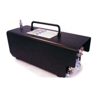
Figure B–1: SS500/SS2000
analyzer externa
l features. B-3
Figure B–2: Fuse location on DC to DC converter. B-4
UK Distibution by IMA Ltd Tel: +44 (0)1943 878877 Email: info@ima.co.uk Web: www.ima.co.uk
 Loading...