36
PHYSICAL TRANSMITTER ADJUSTMENTS
CHANGING FROM RIGHT HANDED TO LEFT HANDED -continued-
The knob/switch I assembly can also be switched with the headphone jack
assembly on the back of the transmitter.
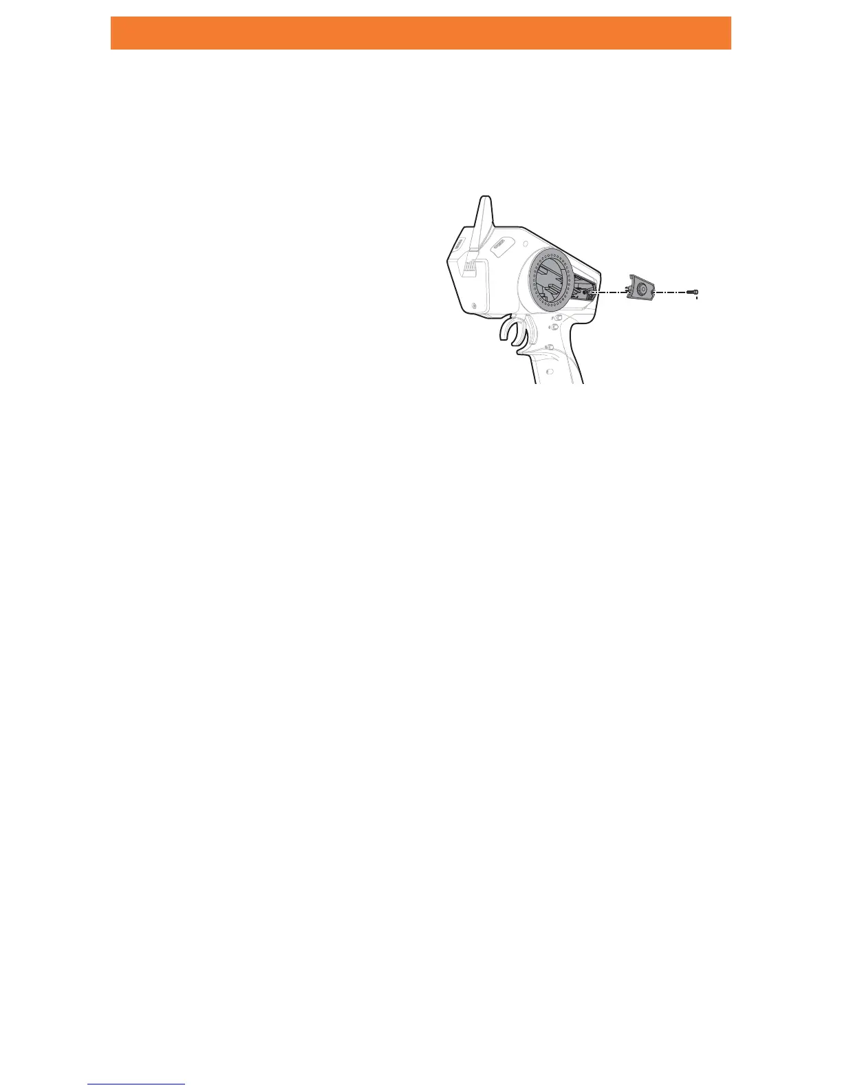
REMOVING THE ASSEMBLIES
• Turn off the DX6R
• Using a small .050 screwdriver,
remove 1 screw from each assembly
• Lift up on each assembly.
• Carefully remove the wiring harness
from the board inside the transmitter.
INSTALLING THE ASSEMBLIES
• Install the assemblies on the
opposite face of the transmitter.
• Connect the wiring harness to the
board inside the DX6R.
• Carefully seat the assemblies into
face of the transmitter being careful
not to pinch any wires.
• Install the one Phillips head screw
into each assembly.
Wiring not shown
IMPORTANT: There is a 4 pin and 5 pin attachment on each side of the
transmitter. The headphone jack connector will use the 4 pin connector and
the Knob/Switch I will use the 5 pin connector.