VisionMaster Ship’s Manual Chapter 3
Installation Bulkhead Transceiver Cabling Information
65900011 3–43
6.3.1 Bulkhead Transceiver Cabling Information
Figure 3.24 shows details of the cable input. The Transceiver cover, which is
secured by four fixing screws, is shown removed. A cable-retainer holds the
coaxial cables in place. The cables must be fitted to the retainer after the
cables are in place.
All other cables, with the exception of the X-band RF feeder (waveguide), are
individually clamped on their cable braids to provide EMC shielding. The
braids are also made off as tails and connected to earth tags supplied.
The AC mains input is connected to TSE located underneath the cover plate
as shown in Figure 3.24.
6.3.1.1 Bulkhead Transceiver Input PCB Details
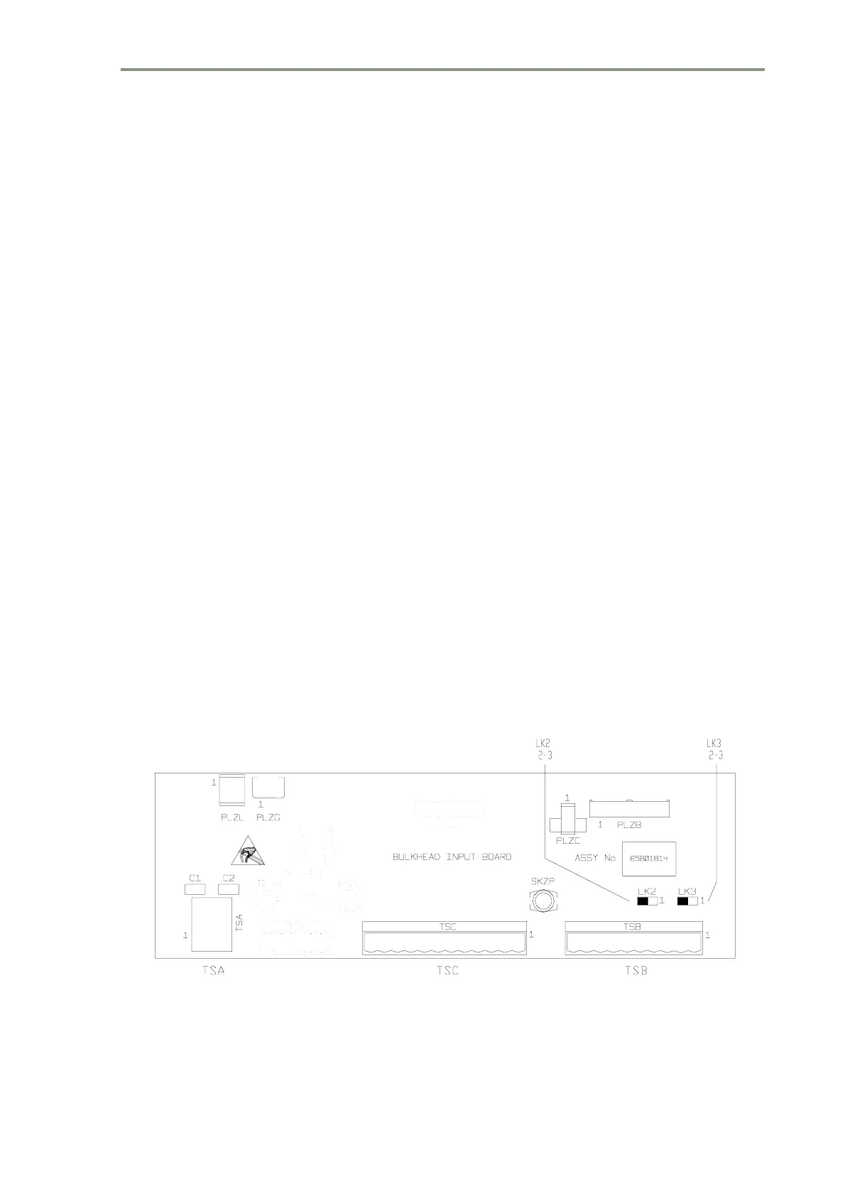
Figure 3.23 shows details of the Input PCB Assembly 65801814.
Access to the board is made by removing the main Transceiver cover and
the Filter Box cover. Refer to the cabling schedules in Section 7 ‘System
Component Interconnections’ for details of the connections, which are made
by using the two-part connectors supplied.
For ‘additional features’ transceivers fitted with PCB 65801815 or
65801821, see Section 3.3 ‘Configuring Printed Circuit Boards.’ in Chapter
11 ‘Additional Features’.
Configuration for normal operation is by link settings as follows:
Figure 3.23 X-band Bulkhead Transceiver - Input Board Details
LK2 Link pins 2 and 3
LK3 Link pins 2 and 3



 To Next Page