Do you have a question about the Sperry Marine VISIONMASTER FT ECDIS-E and is the answer not in the manual?
Explains safety checking features and how they operate in dual-node configurations.
Covers chart types, rendering, accuracy factors, overscale indications, and chart tools.
Details chart databases, enabling/disabling, auto-scale preferences, and supported chart engines.
Covers chart updates summary, installation, copy, permissions, index, and error messages.
Covers creating, editing, adding, deleting, realigning, copying, and exporting PI lines.
Details creating, editing, saving, monitoring, importing, and exporting clearing lines.
Explains determining ship's geographic location using LOPs and creating fixes.
Manages MOB emergencies, providing location, bearing, range, and elapsed time data.
Allows selection of sensor sources for data types like heading, speed, and position.
Shows geodetic position data, sensor sources, and explains dead reckoning values.
Details alert priorities (Alarms, Warnings, Cautions) and their indication methods.
Explains the alert status indicator, display of active alerts, and acknowledgment procedures.
Provides comprehensive tables of all system alarms, warnings, and cautions with descriptions.
Guides on creating routes, adding waypoints, inserting waypoints, and changing positions.
Covers saving, validating, opening, clearing, deleting routes, and using the editor table.
Enables calculation of ETA, speed, and distance between waypoints for route planning.
Details creating, editing, monitoring temporary routes, and transitioning them to monitored routes.
Enables creating critical points and viewing dangers or cautions along a route for safety.
Details AIS targets, rendering conditions, display capacity, and activation when limits are reached.
Describes method for accurately setting the monitor's brightness control to an optimal setting.
| Power Supply | 24 VDC |
|---|---|
| Chart Format Support | S-57, S-63 |
| Radar Overlay | Yes |
| AIS Target Display | Yes |
| User Charts | Yes |
| Route Planning | Yes |
| Route Monitoring | Yes |
| Alert Management | Yes |
| ECDIS Type | ECDIS |
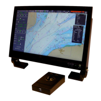
| Display Type | Color LCD |
| Resolution | 1920 x 1200 pixels |
| Operating System | Windows |
| Processor | Intel Core i5 |
| Storage | SSD |
| Connectivity | Ethernet, USB |
| Certification | IMO, IEC |
| Input Method | Keyboard, Trackball |
| Integration | Radar, AIS |
| Compliance | IMO |