Chapter 10 VisionMaster Ship’s Manual
Installation and Commissioning Interswitch Units
10–8 65900011
4 Installation and Commissioning
4.1 Siting Considerations
The maximum separation between the Interswitch and an operating display
should not exceed 12 metres. (i.e. if only one display in the system may be
functioning, and the other displays are turned off; the distance between the
interswitch and the display that is functioning must not exceed 12 metres).
If this is not practicable to achieve, then an additional cable should be used for
the +/-12V power connection between the interswitch and the display.
4.2 Interswitch Hardware Configuration
4.2.1 Dil Switches
In order to indicate which Displays and Transceivers are connected to the
Interswitch, set the appropriate switches to the ‘off’ position.
On the 2-Way Interswitch PCB board there are two 4-way DIL switches. SW1
selects Display Units while SW2 selects Transceivers.
On the 6-Way Interswitch PCB board there are two 6-way DIL switches. SW1
selects Display Units while SW2 selects Transceivers.
Link 1 selects LOCAL or GLOBAL setting. If the system is in the Local Mode,
a Display Unit can only change the Transceiver to which it is connected and
select either master or slave mode. If the system is in the Global Mode, any
display can completely re-configure the entire system.
Inserting Link 2 at position 2-3 loads the default settings at power-up. For a
2-way Interswitch that is fully populated, the default state will be as shown
below:
• DUA master to TXA DUB master to TXB
• DUC slave to TXA DUD slave to TXA
For a 6-way Interswitch the default setting will be one to one connection.
Links 3 & 4 are for test and diagnostic purposes only.
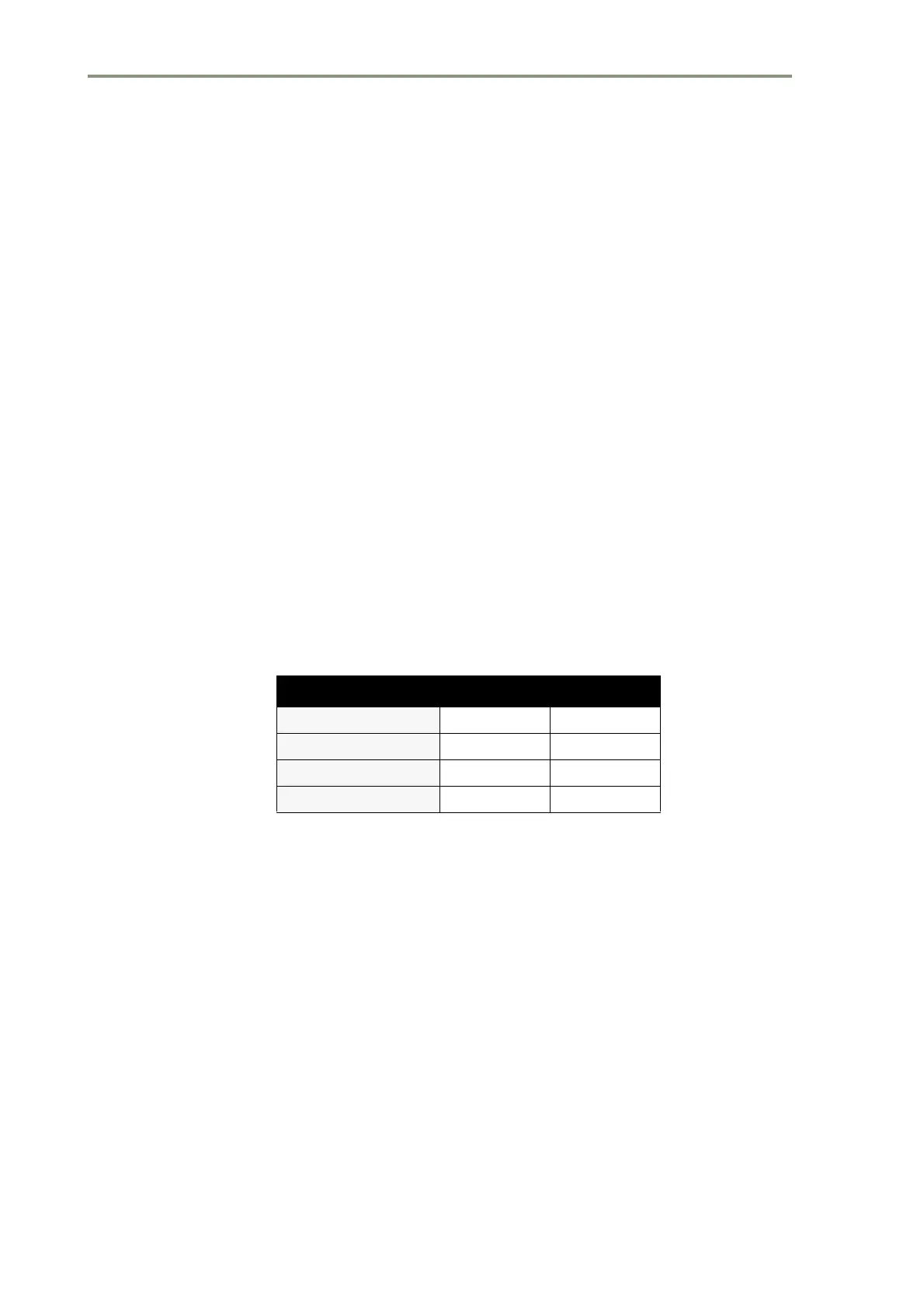
Table 1: Link Settings 1 & 2
Mode Link Setting
Global
LK1 2-3
Local
LK1 1-2
Normal
LK2 12
Reset Defaults
LK2 2-3