Maintenance Waukesha Cherry-Burrell
Page 36 95-03009 10/2010
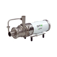
14. Check the space between the back of the impeller and the backplate
with a feeler gauge (0.030" nominal) while holding the backplate tight
against the bearing housing flange. (Any axial movement of the shaft
should not be added to the 0.030" nominal clearance) (Figure 33). If
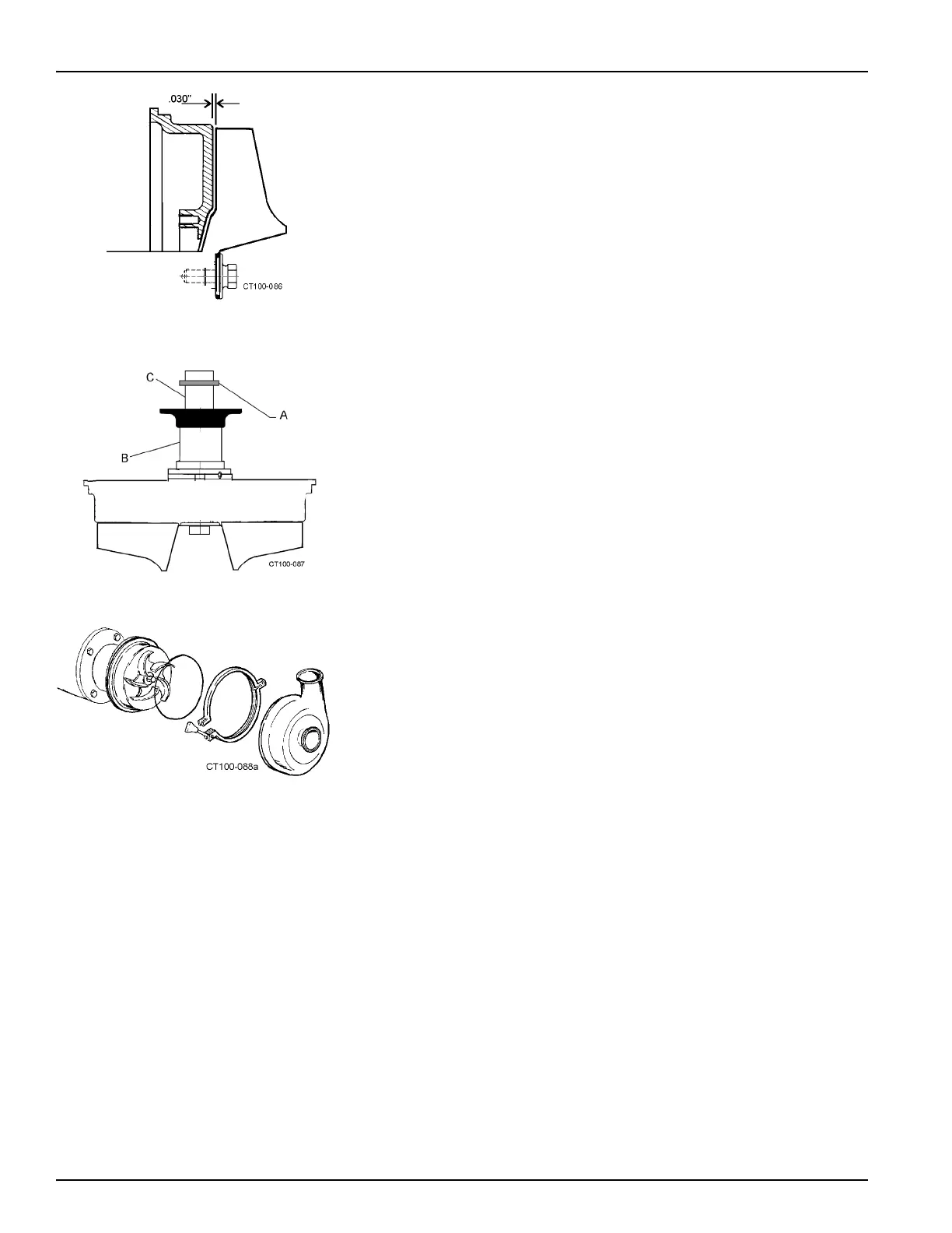
needed, change this clearance by adding or removing shims. Shims
(Figure 34, item A) are added on the drive shaft (Figure 34, item C)
behind the impeller shaft (Figure 34, item B).
15. Confirm the operating clearances b
y
clamping the casing to the bear-
ing housing flange and rotating the shaft/impeller manually to be sure
the
impeller does not touch the casing or backplate.
16. When the proper shim pack is confirmed, remove the casing, impel-
ler, and backplate, leaving the shim pack on the shaft.
17. Remove the backplate/impeller assembly and apply anti-seize or
equal compound to the motor shaft and install the key.
NOTE: Always re
place the o-rings and L-gasket when reassembling the
pump. If the area behind these seals becomes soiled, contact WCB Appli-
cation Engineering for a specific cleaning and sanitizing procedure vali-
dated to remove bacteria.
18. Install the casing o-ring on the backplate and clamp the casing in
pla
c
e (Figure 35).
NOTE: Rotate the impeller manually to ensure it does not rub on the
ba
ckplate or casing.
Figure 33 - Clearance Between Impeller
and Backplate
Figure 34 - Locations of Shims
Figure 35 - Install Casing