Chapter 3. Identifying the Components
May 2002 T-38324-A Page 3-13
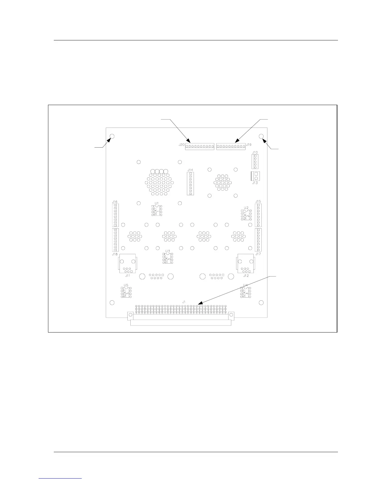
I/O Board
The I/O board shown in Figure 3-9 is inserted into a connector, J2, on the backplane. It interfaces to
all of the connectors available on the bottom of the controller, see Figure 3-3 on page 3-4. On the top
side of the I/O board are some diagnostic connections (J19 and J20) for digital I/O.
Figure 3-9. I/O Board
Power Supply
A 1.2A, 24V power supply provides power for the TCM I/O and Ethernet interface card.
Digital I/O Connector, J20 Digital I/O Connector,
J19
Ground
Mounting Hole
Ground
Mounting Hole
I/O Connector, J1