CS4000 Mini Controller with Ethernet
Page
4-8
T-38324-A 39-30-38324
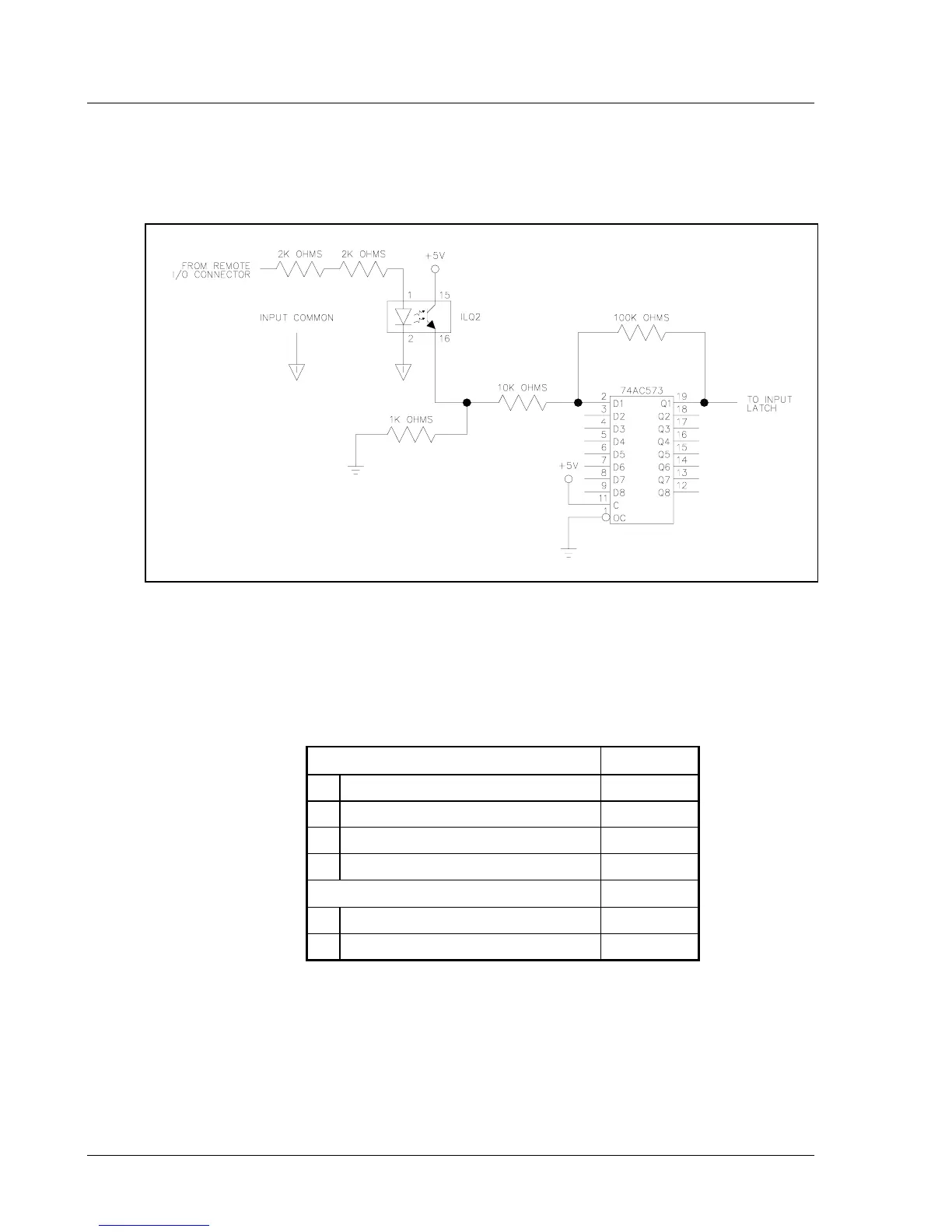
A remote input circuit schematic and remote I/O schematics for sourcing and sinking outputs are
shown in Figure 4-3 through Figure 4-5.
Figure 4-3. Remote Input Circuit Schematics
To ensure that you operate the fastening system properly, refer to Table 4-2 for input requirements.
Table 4-2. Guidelines for Proper Operation of the Controller I/O Signals
Discrete Inputs Unit
Highest permissible input voltage 30 V
Lowest permissible input voltage -5 V
Minimum guaranteed input activation 10 V
Maximum guaranteed input activation 1.5 V
Discrete outputs Unit
Maximum output current 360 mA
Maximum voltage 28 Volts DC