Installation Waukesha Cherry-Burrell
Page 26 95-03080 12/2010
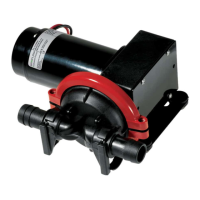
Flush Seal Option When this option is ordered, a fitting assembly (Figure 20, item A)
is supplied for directing a flow of water onto the backplate/seal
area.
• The water cascade block must be above the seal on the
assembled backplate to flow water onto the seal face.
• The connection (Figure 20, item B) is 1/4 inch O.D. tubing.
• The required flow is approximately 5 U.S. gallons per hour.
• The recommended water supply is cool and filtered. If the
pr
oduct solidifies at cool temperature, warm or hot water can
be used.
NOTE: To prevent hose contact with the rotating shaft and seal
parts during operation, pull any excess hose to the outside of the
seal guard.
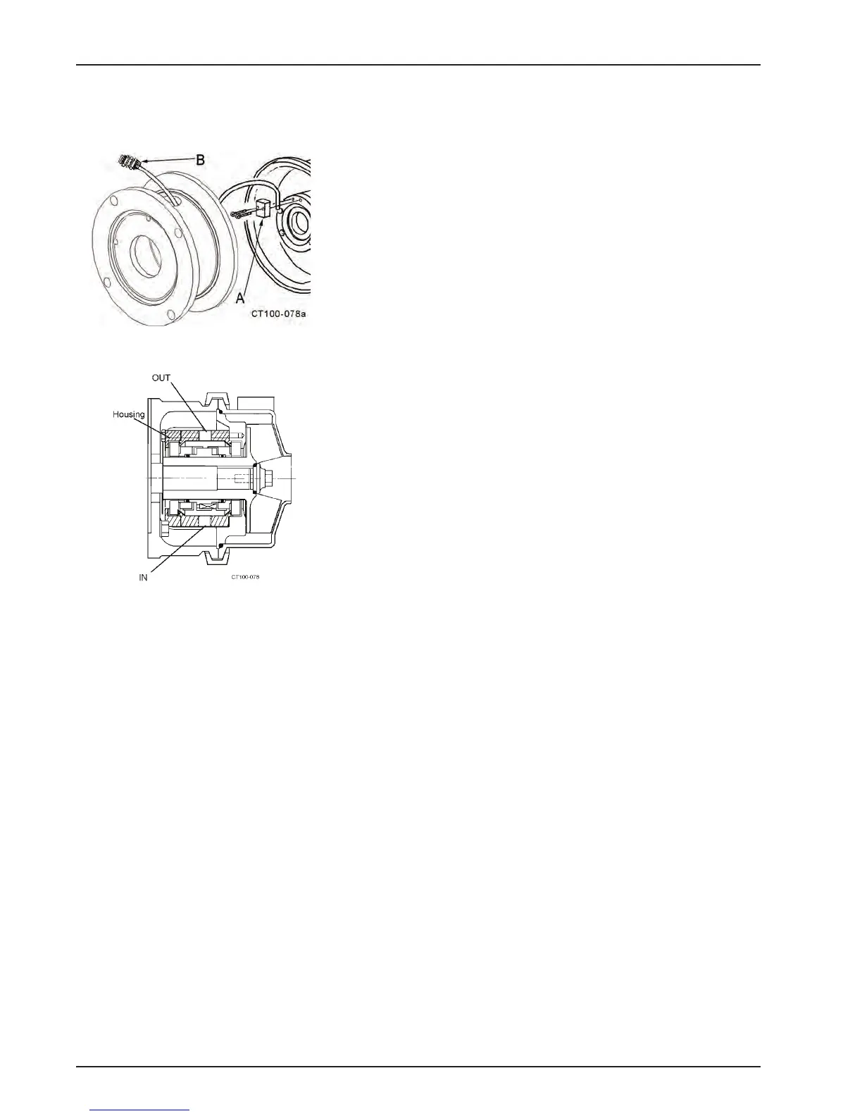
Type 4 Seal (Double mechanical with flush)
Attach the seal flush supply to the bottom 1/4-inch pipe threaded
hole in the flush housing. The drain tubing attached to the top hole
allows moderate pressure to be supplied to the seals and allows
continuous flooding. See Figure 21.
Before First Startup Clean Pump and Piping
Disassemble pump and clean all product contact parts and seal
parts prior to first operation. Follow instructions in the “Cleaning
Safety Procedures” on page 27 and “Routine Maintenance” on
page 28. The pump should be thoroughly cleaned of any materi-
als which could have accumulated during installation.
Figure 20 - Cascade System Installation
Figure 21 - Type 4 Flush Housing