Waukesha Cherry-Burrell Maintenance
12/2010 95-03080 Page 43
Pre-assembled (Cartridge)
Seals
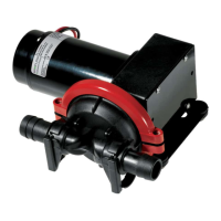
Figure 53 - Remove Casing Clamp,
Casing and o-ring
.
Figure 54 - Removal of Wet End
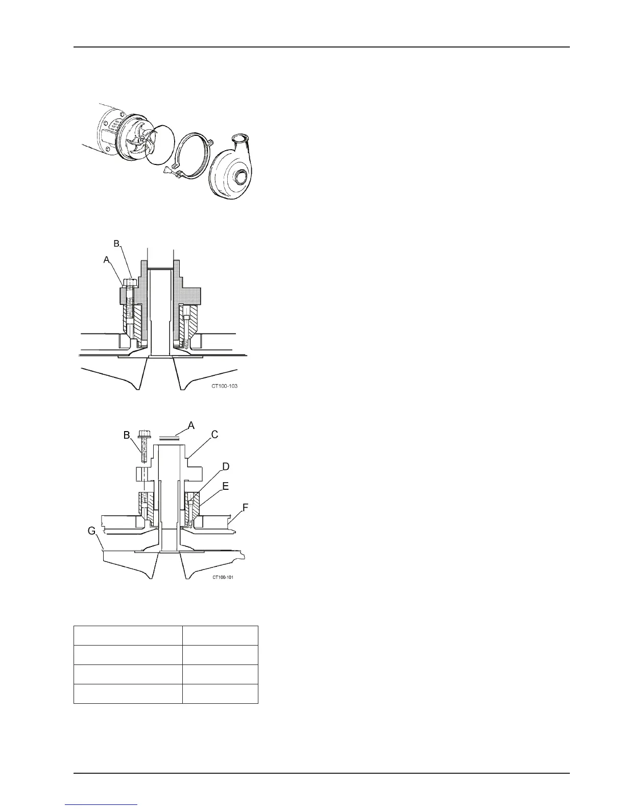
Figure 55 - Remove Seal Assembly.
Pre-assembled (Cartridge) seals have all the seal components
mounted to a flange, and are pre-adjusted at the factory. Follow
the seal manufacturer's (John Crane, A. W. Chesterton, etc.) rec-
ommendations regarding application
,
operation, and mainte-
nance.
NOTE: The cartridge seal comes with a set of removable lugs/
spacers in place that are used to hold the assembly together until
installation is final. Do not remove these lugs until installation is
complete and you are instructed to do so on page 45 in step 17.
Disassembly of Pre-assembled (Cartridge) Seals
The following procedure covers the disassembly of pre-assem-
bled (cartridge) seals.
1. Remove all flush connections and fittings.
2. Remove the casing clamp, casing and o-ring from the hous-
ing flange. See Figure 53.
3. Remove the impeller retainer nut and o-ring; then loosen the
seal set
screws. (Figure 54, item A).
4. Pull the impeller, backplate and seal off the bearing shaft as a
un
it. Set th
e assembly face down (on the impeller).
NOTE: T
he clearance shims that position the impeller within the
casing
are at the end of the impeller hub (inside the seal.) Keep
shims together as a set for reassembly. See Figure 55.
5. Remove cap screws (Figure 55, item B) holding the cartridge
seal to the seal adapter. (See Figure 55, items C and E).
6. Remove seal unit from the backplate assembly.
7. Pull seal from seal adapter. (See Figure 55, items C and E).
8. Remove seal adapter by removing socket head cap screws
(Figure 55, item D) holding adapter to the back plate.
Table 17: Callouts for Figure 55
A. Shims E. Adapter
B. Cap Screw F. Backplate
C. Cartridge Seal G. Impeller
D. Socket Head Screw