Maintenance Waukesha Cherry-Burrell
Page 38 95-03080 12/2010
Pump Assembly with Type
4 Double Seal
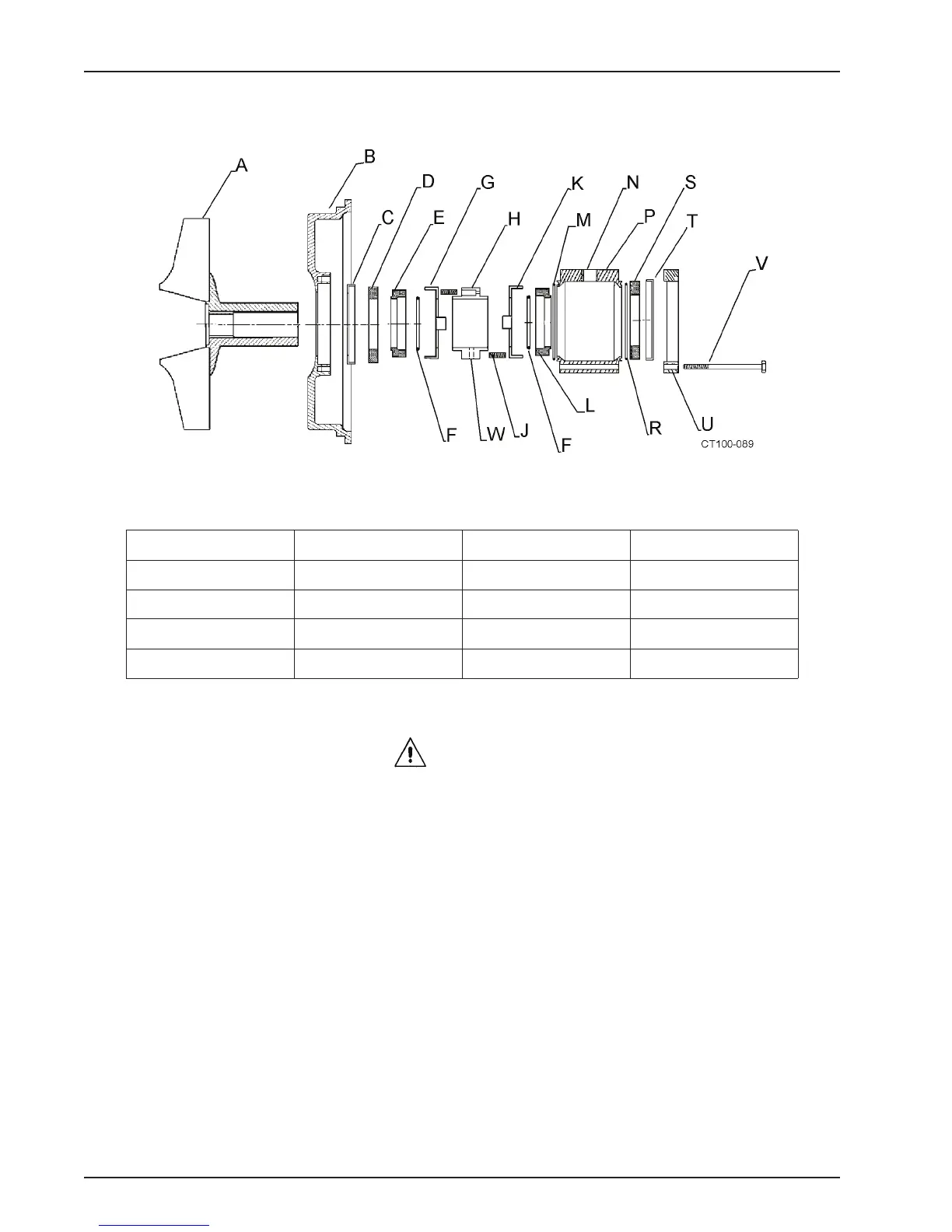
Figure 41 - Type 4 Seal Components
Table 16: Callouts for Figure 41
A. Impeller F. O-ring L. Rotary Seal S. Stationary Seal
B. Backplate G. Washer M. O-ring T. L-gasket
C. L-gasket H. Spring Retainer N. NPT Port U. Seat Retainer
D. Stationary Seal J. Spring P. Flush Housing V. Hex Head Screw (4)
E. Rotary Seal K. Washer R. O-ring W. Set Screw
1. Clean all parts and lubricate all elastomer (Rubber-like) parts
CAUTION:
Handle the impeller/backplate assembly with
care to prevent damage to the seal components.
2. Install L-gasket in backplate. (See Figure 41, items B and C).
3. Install L-gasket in seat retainer. (Figure 41, item T).
4. Install stationary seals (Figure 41, item S) in L-gaskets.
5. Place backplate and rotary seal onto impeller shaft.