Waukesha Cherry-Burrell Maintenance
12/2010 95-03080 Page 33
Pump Assembly with Type
1 Seal
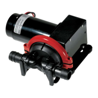
Figure 30 - Stationary Seal Assembly
Backplate Assembly
1. Lightly lubricate both sides of the L-gasket (Figure 30, item D)
with a sanitary lubricant and insert into the backplate seal
cavity.
2. Place the stationary seal into the L-gasket. (See Figure 30,
items C and D).
3. Place the seat retainer over th
e stationary seal and secure
the retainer with four 1/4-20 x 1/2 inch hex head cap screws.
(See Figure 30, items B and A).
4. Tighten the cap screws evenly.
Backplate/Impeller Assembly
1. Place the impeller on a clean flat surface, shaft end up, and
slide the assembled backplate onto the impeller shaft.
NOTE: Avoid
hitting
the stationary seal against the impeller shaft,
as this could break the seal.
2. Carefully place the rotary seal in position over the impeller
shaft and down against the stationary seal.
3. Lubricate and slide the seal o-ring onto the impeller shaft.
(
U
se the spring retainer as a tool to push the o-ring into the
rotary seal). See Figure 31.
4. Slide the tabbed washer (Figure 30, item F) over the impeller
shaft and engage the tabs of the washer into notches on the
outside of rotary seal. (See Figure 32, items F and H ).
5. Install the three seal springs into
th
e holes in the spring
retainer (See Figure 32, items C and E). Hold the springs in
place with RTV silicone sealant.
6. Slide the spring retainer over the impeller shaft until the slots
in
the spring retainer engage the drive tabs on washer and
the springs rest against the washer. See Figure 32.
7. With the backplate against the impeller, push the spring
retainer down to c
ompress the springs until the length of visi-
ble spring is approximately 1/8".
8. Lock the spring retainer in place
by tightening the set screws.
(Figure 32, item D).
9. Install the deflector onto the impeller shaft (Figure 32, item
B).
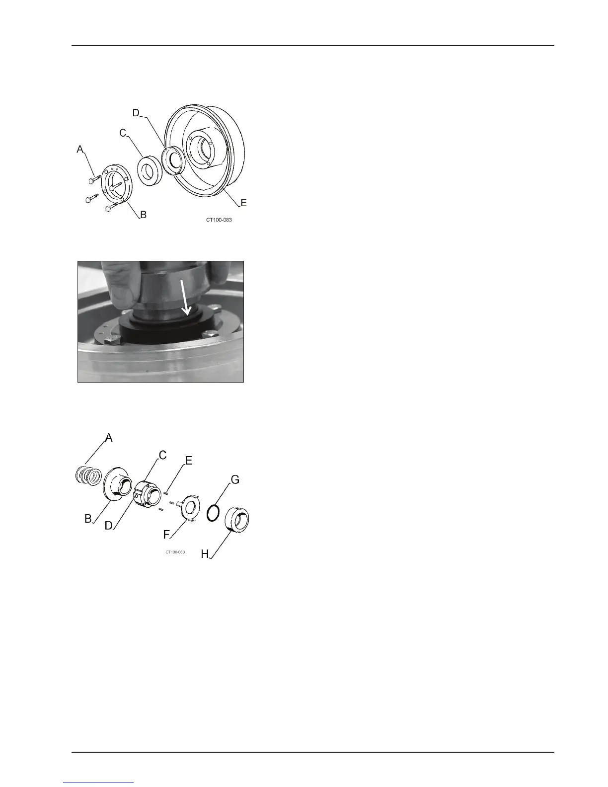
Figure 31 - Installing o-ring Using the
Spring Retainer.
Figure 32 - Type 1 Seal Assembly