Maintenance Waukesha Cherry-Burrell
Page 42 95-03080 12/2010
Disassembling The Outer Seal Assemblies
1. Using a 1/8" hex wrench, loosen the set screws (Figure 50,
item A).
NOTE: Th
e set screws are located opposite the grease fittings in
the adapter or end cap.
2. Remove the impeller end of the bearing housing. (Figure 50,
item B).
3. Remove the outer seal ring assemblies (the inner seal ring
an
d o-rings). See Figure 50 and Figure 51.
Assembling the Outer Seal Assemblies
Reverse the above disassembly procedure with the added step
of installing new o-rings in the seal rings.
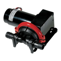
NOTE: Figure 51 shows the seal position at the motor end. Seals
at the pump end face inward. Make sure to tighten tthe set
screws when installing the outer seal assemblies. See Figure 52.
NOTE: Replace all rubber parts whenever a unit is dismantled for
inspection or repair. Lubricate rubber parts with an approved/san-
itary lubricant prior to assembly.
Figure 50 - Remove Set Screws
Figure 51 - Seal Configuration
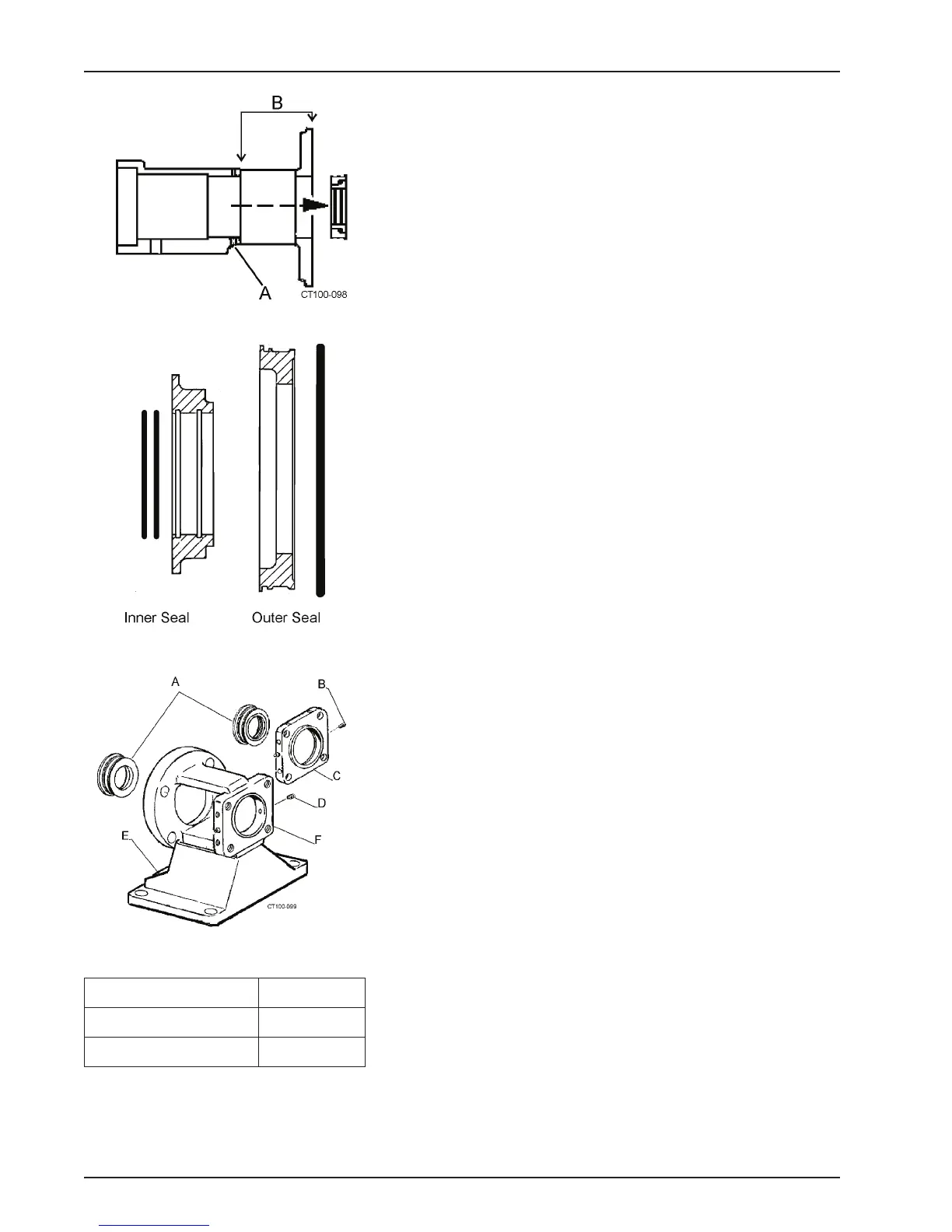
Figure 52 - Outer Seal Assemblies
A. Outer Seal Assembly D. Set Screw
B. Set Screw E. Adapter
C. End Cap F. Stand