Maintenance Waukesha Cherry-Burrell
Page 44 95-03080 12/2010
Assembly of a Pump With Pre-assembled
(Cartridge) Seals
1. Place the shims, backplate and impeller on the shaft assem-
bly. Hand tighten the impeller retainer bolt on the shaft.
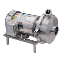
2. Check the impeller/backplate clearance with the backplate
h
e
ld firmly in position against the motor adapter. Check the
space between the back of the impeller and the backplate
with a feeler gauge (.030 nominal) while holding the back-
plate tight against the bearing housing flange. (Any axial
mo
vement of the shaft should not be added to the .030 nomi-
nal clearance). See Figure 56. If needed, change this clear-
ance by adding or removing shims. Shims (Figure 55, item A)
can be added on the drive shaft behind the impeller shaft
(Figure 55, item G).
3. Confirm operating clearances by cl
amping the casing to the
bearing housing flange and rotating the shaft/impeller manu-
ally to be sure the impeller does not touch the casing or back-
plate.
4. When the proper shim pack is confirmed, remove the casing,
imp
eller and backplate, leaving the shim pack on the shaft.
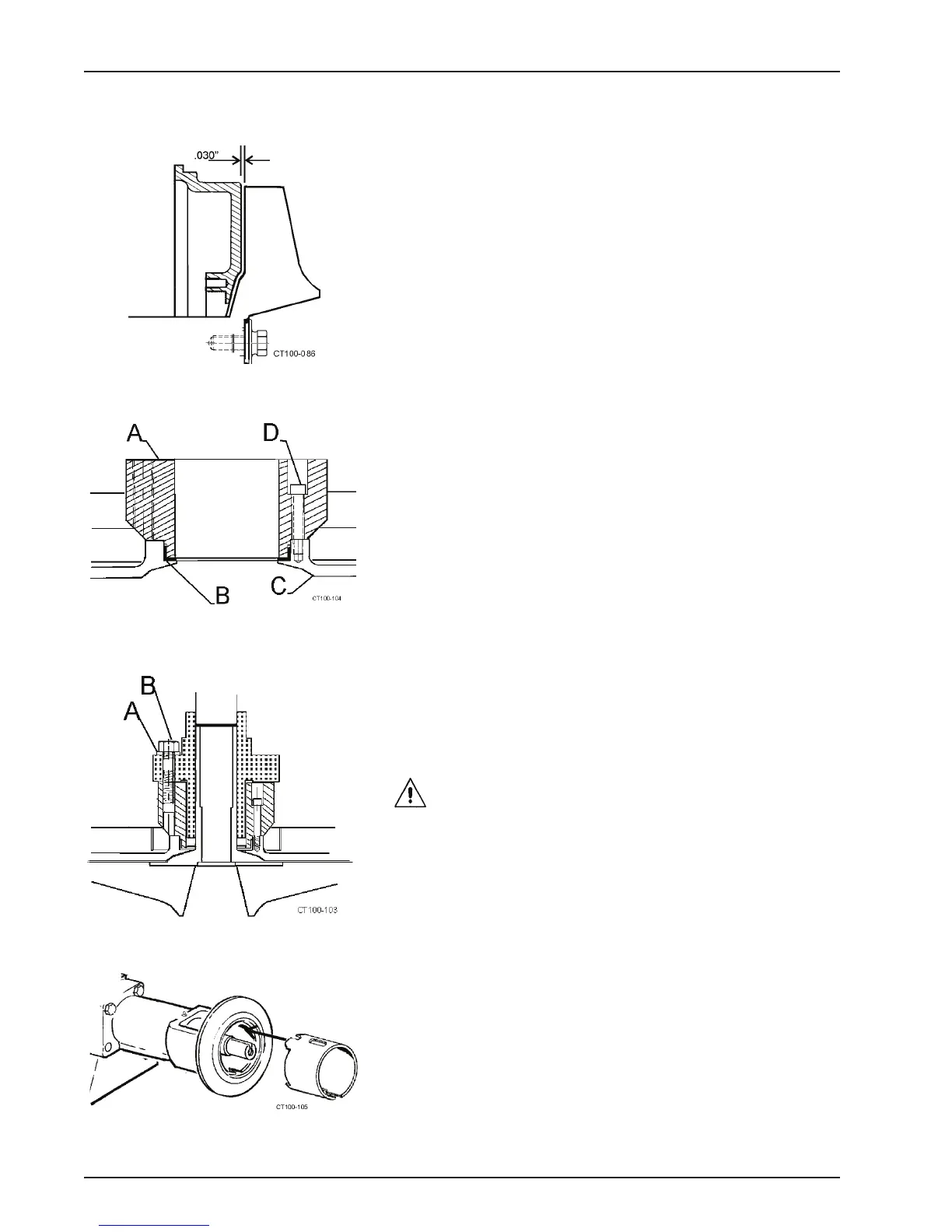
5. Insert the L-gasket into the backplate. (See Figure 57, items
B and C).
6. Insert the cartridge adapter (Figure 57, item A) into the back-
plate (item C) and tighten with four socket head cap
sc
rews.(item D).
7. Install the cartridge seal unit and use the retaining bolts (Fig-
ure 58, item B) and flat washers (Figure 58, item A) to secure
the unit to the cartridge adapter. Make sure not to tight
en the
retaining bolts yet.
CAUTION:
Be sure the removable lugs/spacers that posi-
tion the rotating part of the seal in the housing are in place
at this time.
8. Apply an FDA-approved anti-seize compound to the shaft.
9. Install and position the seal guard. See Figure 59.
10. Slide the impeller, backplate and seal unit onto the shaft.
NOTE: Be su
re the flushing ports in the cartridge seal are posi-
tioned with the inlet toward the bottom and the outlet toward the
top. (Figure 61, item C).
Figure 56 - Clearance Between Impeller
and Backplate
Figure 57 - Insert L-gasket and Fasten
Adapter in Place
Figure 58 - Fasten Seal Unit in Place
Figure 59 - Installing the Guard