Waukesha Cherry-Burrell Maintenance
12/2010 95-03080 Page 45
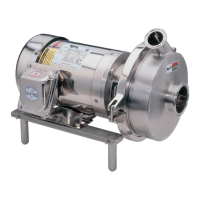
11. Install the impeller key. (Figure 60, item A).
12. Install the o-ring on the impeller retainer bolt. (Figure 60, item
C).
13. Install the impeller retainer nut and tighten. (Figure 60, item
B).
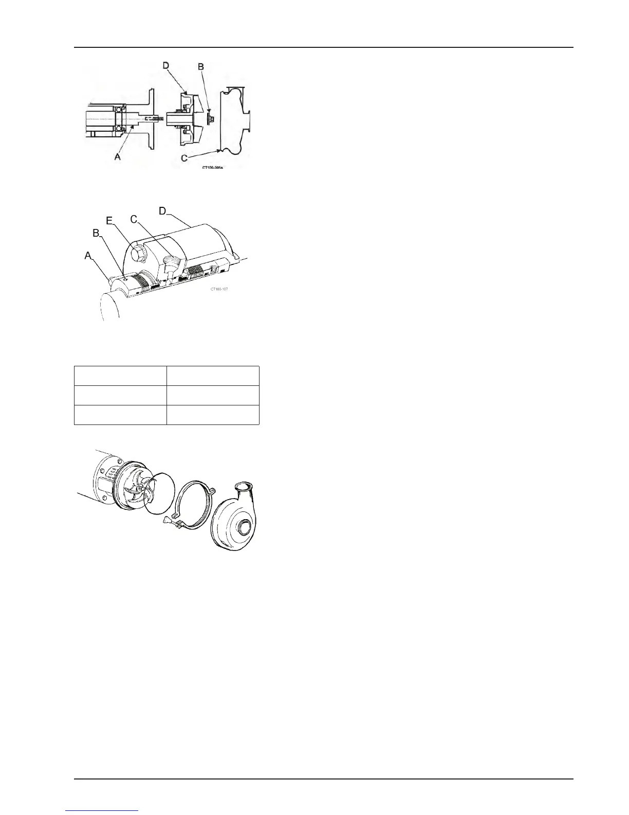
14. Hold the backplate in place and tighten the cartridge seal into
the cartridge adapter by tightening the cap screws (Figure 61,
item E).
NOTE: Th
e backplate and seal can be rotated to give access to
the bolts through the holes in the guard.
15. Install the o-ring and casing; clamp in place. See Figure 62.
16. Tighten the two set screws to the shaft. (Figure 61, item B).
17. Remove the lugs/spacers. (Figure 61, item A).
NOTE: Keep
the lugs/spacers to reinstall on the seal cartridge if
removal is ever required.
18. Connect the flushing fluid and flood the seal.
19. Turn the shaft manually to be sure shaft rotates without the
imp
eller hitting or binding.
Figure 60 - Installing Impeller Assembly
Figure 61 - Typical Cartridge Seal
Table 18: Call Outs For Figure 61
A. Lugs/Spacers D. Seal Adapter
B. Set Screw (2) E. Cap Screws
C. Flush Pots
Figure 62 - Install o-ring, Casing And
Clamp