Power supplies AN4488
14/44 DocID026304 Rev 3
2.3.5 NRST circuitry example (for STM32F411xx and STM32F446xx only)
This example applies to STM32F411xx and STM32F446xx where PDR_ON can be
connected to VSS to permanently disable internal reset circuitry.
Restrictions:
• PDR_ON = 0 is mostly intended for V
DD
supply between 1.7 V and 1.9V (i.e. 1.8V +/-
5% supply).
Supply ranges which never go below 1.8V minimum should be better managed by
internal circuitry (no additional component needed, thanks to fully embedded reset
controller).
• When the internal reset is OFF, the following integrated features are no longer
supported:
– The integrated power-on reset (POR) / power-down reset (PDR) circuitry is
disabled.
– The brownout reset (BOR) circuitry must be disabled.
– The embedded programmable voltage detector (PVD) is disabled.
– VBAT functionality is no more available and VBAT pin should be connected to
V
DD
.
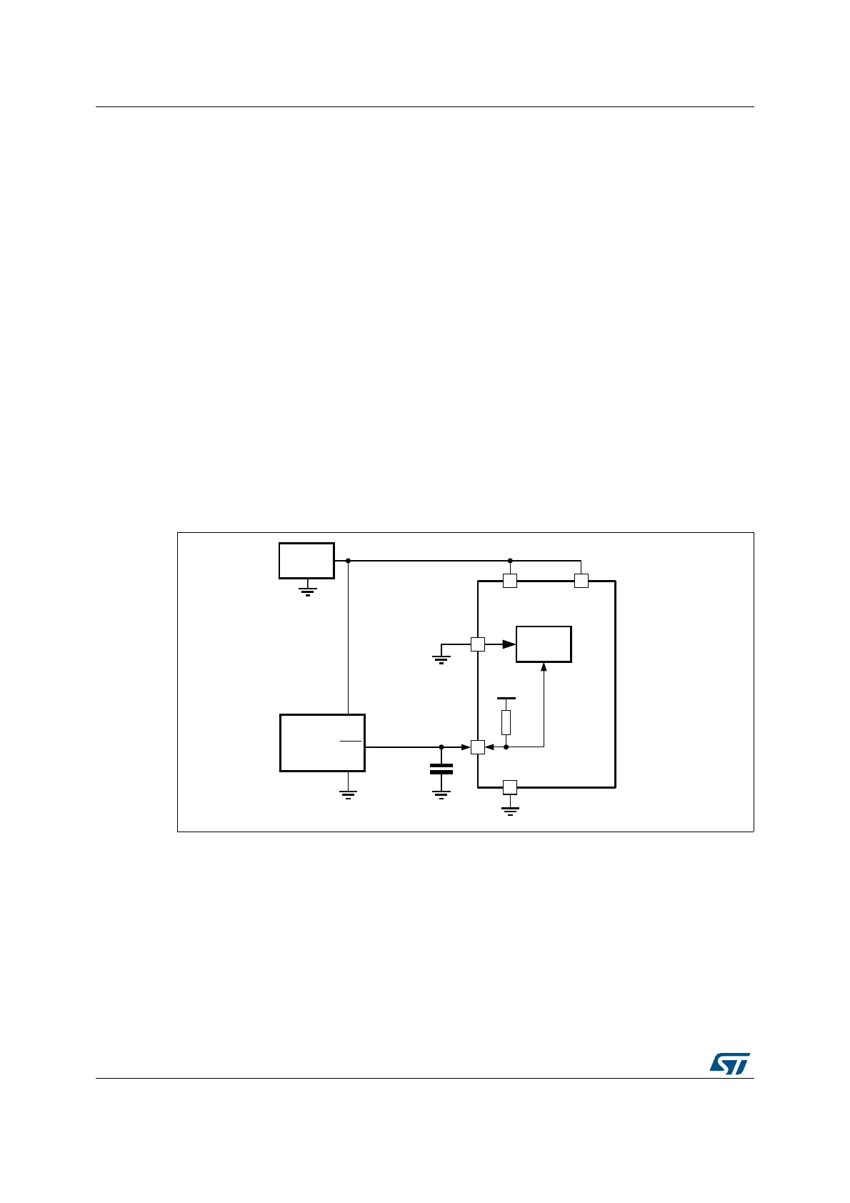
Figure 7. NRST circuitry example
(only for STM32F411xx and STM32F446xx)
Even with PDR_ON=0, during power up, the NRST is driven low by internal Reset controller
during T
RSTTEMPO
in order to allow stabilization of internal analog circuitry. Refer to
STM32F4xxxx datasheets for actual timing value.
670)
3'5B21
5HVHW
FRQWUROOHU
9ROWDJH
UHJXODWRU
9W\S9PLQ
1567
Nȍ
)
9ROWDJH
VXSHUYLVRU
DFWLYHORZRSHQGUDLQRXWSXW
287
6701
069
9
''
9
''$
9
%$7
9
''
9
66
9
66$

 Loading...


