Boot configuration AN4488
30/44 DocID026304 Rev 3
5 Boot configuration
5.1 Boot mode selection
In the STM32F4xxxx, three different boot modes can be selected by means of the
BOOT[1:0] pins as shown in Table 7.
The values on the BOOT pins are latched on the 4
th
rising edge of SYSCLK after a reset. It
is up to the user to set the BOOT1 and BOOT0 pins after reset to select the required boot
mode.
The BOOT pins are also resampled when exiting the Standby mode. Consequently, they
must be kept in the required Boot mode configuration in the Standby mode. After this startup
delay has elapsed, the CPU fetches the top-of-stack value from address 0x0000 0000, and
starts code execution from the boot memory starting from 0x0000 0004.
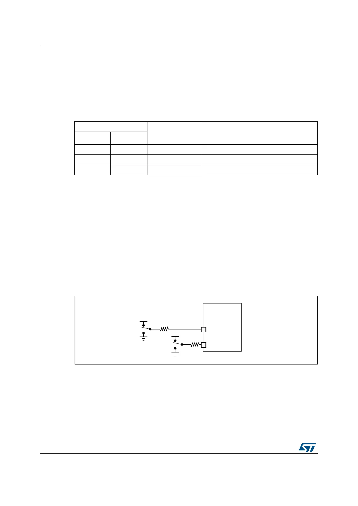
5.2 Boot pin connection
Figure 22 shows the external connection required to select the boot memory of the
STM32F4xxxx.
Figure 22. Boot mode selection implementation example
1. Resistor values are given only as a typical example.
Table 7. Boot modes
BOOT mode selection pins
Boot mode Aliasing
BOOT1 BOOT0
x 0 Main Flash memory Main Flash memory is selected as boot space
0 1 System memory System memory is selected as boot space
1 1 Embedded SRAM Embedded SRAM is selected as boot space
06Y9
9''
670)[[[[[
%227
%227
9''
N
N

 Loading...


