Debug management AN4488
34/44 DocID026304 Rev 3
To avoid any uncontrolled I/O levels, the STM32F4xxxx embeds internal pull-up and pull-
down resistors on JTAG input pins:
• JNTRST: Internal pull-up
• JTDI: Internal pull-up
• JTMS/SWDIO: Internal pull-up
• TCK/SWCLK: Internal pull-down
Once a JTAG I/O is released by the user software, the GPIO controller takes control again.
The reset states of the GPIO control registers put the I/Os in the equivalent state:
• JNTRST: Input pull-up
• JTDI: Input pull-up
• JTMS/SWDIO: Input pull-up
• JTCK/SWCLK: Input pull-down
• JTDO: Input floating
The software can then use these I/Os as standard GPIOs.
Note: The JTAG IEEE standard recommends to add pull-up resistors on TDI, TMS and nTRST but
there is no special recommendation for TCK. However, for the STM32F4xxxx, an integrated
pull-down resistor is used for JTCK.
Having embedded pull-up and pull-down resistors removes the need to add external
resistors.
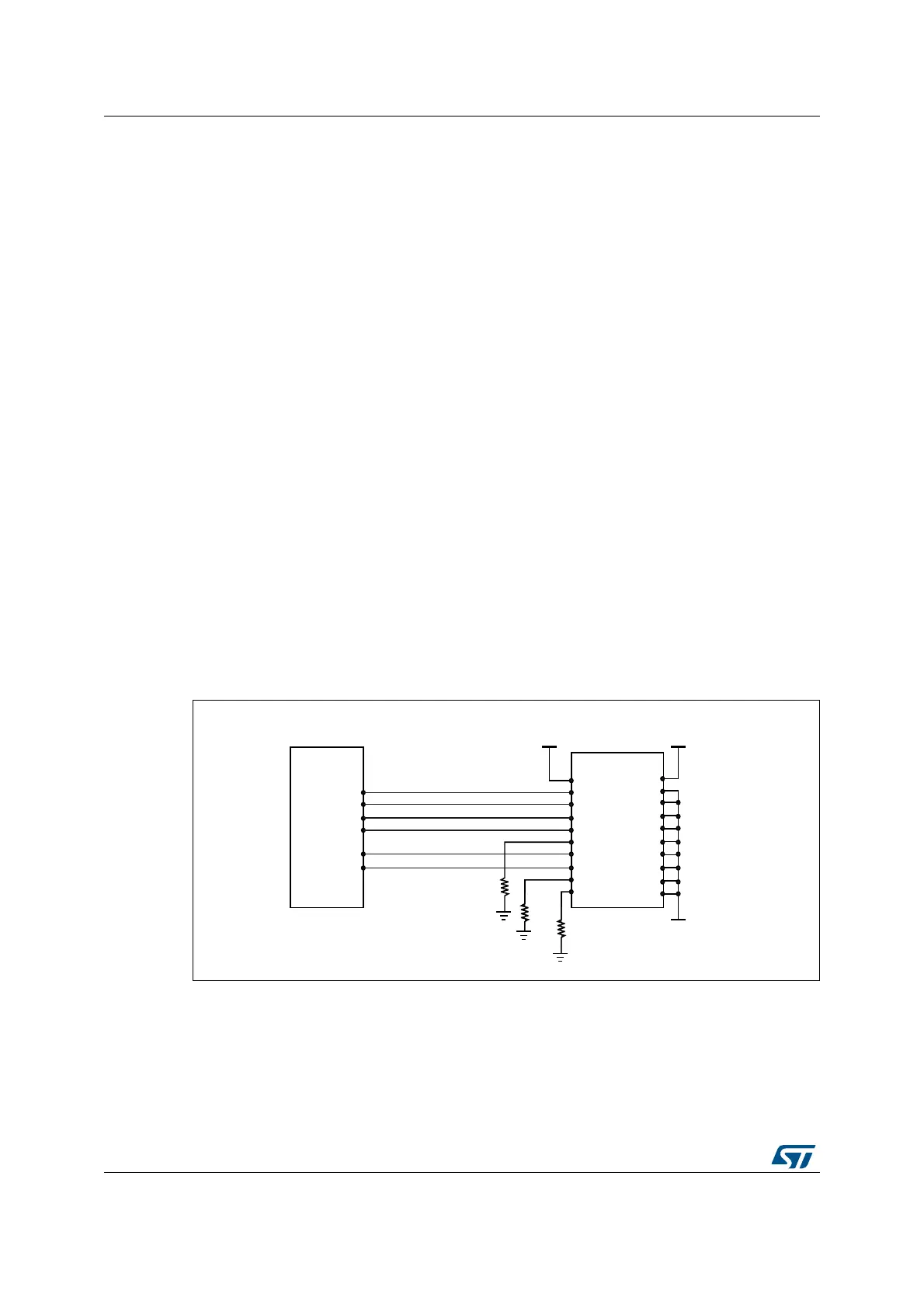
6.3.4 SWJ debug port connection with standard JTAG connector
Figure 24 shows the connection between the STM32F4xxxx and a standard JTAG
connector.
Figure 24. JTAG connector implementation
069
9
''
9
''
670)
Q-7567
-7',
-6706:',2
-7&.6:&/.
-7'2
Q567,1
975()
Q7567
7',
706
7&.
57&.
7'2
Q6567
'%*54
'%*$&.
N
N
N
9
66
&RQQHFWRUî
-7$*FRQQHFWRU&1

 Loading...


