8.2.2 Supplying the STM32H7B3I-DK using the external power supply input from VIN (7 to 12 V,
800mA max)
It can happen that the STM32H7B3I-DK board requires more than 500 mA of supply current. In such a case, the
board can be supplied through pin8 (marked VIN on the board) of the CN19 ARDUINO
®
connector.
Note that using STLINK-V3E for debugging when powering the board with an external power supply, it is
important to power the board before connecting the host PC to CN14, which requires the following sequence to
be respected:
1. Set the jumper between the pins 7-8 of JP1 “ARD”.
2. Connect the external power source to pin8 of CN19.
3. Check that the green LED LD5 is turned ON.
4. Connect the host PC to USB connector CN14.
If this order is not respected, the board may be powered by VBUS first from STLINK, and the following risks may
be encountered:
1. If more than 500 mA current is needed by the board, the PC may be damaged or the current can be limited
by PC. As a consequence, the board is not powered correctly.
2. 500 mA is requested at the enumeration step, so there is a risk that the request is rejected and enumeration
does not succeed if PC cannot provide such current.
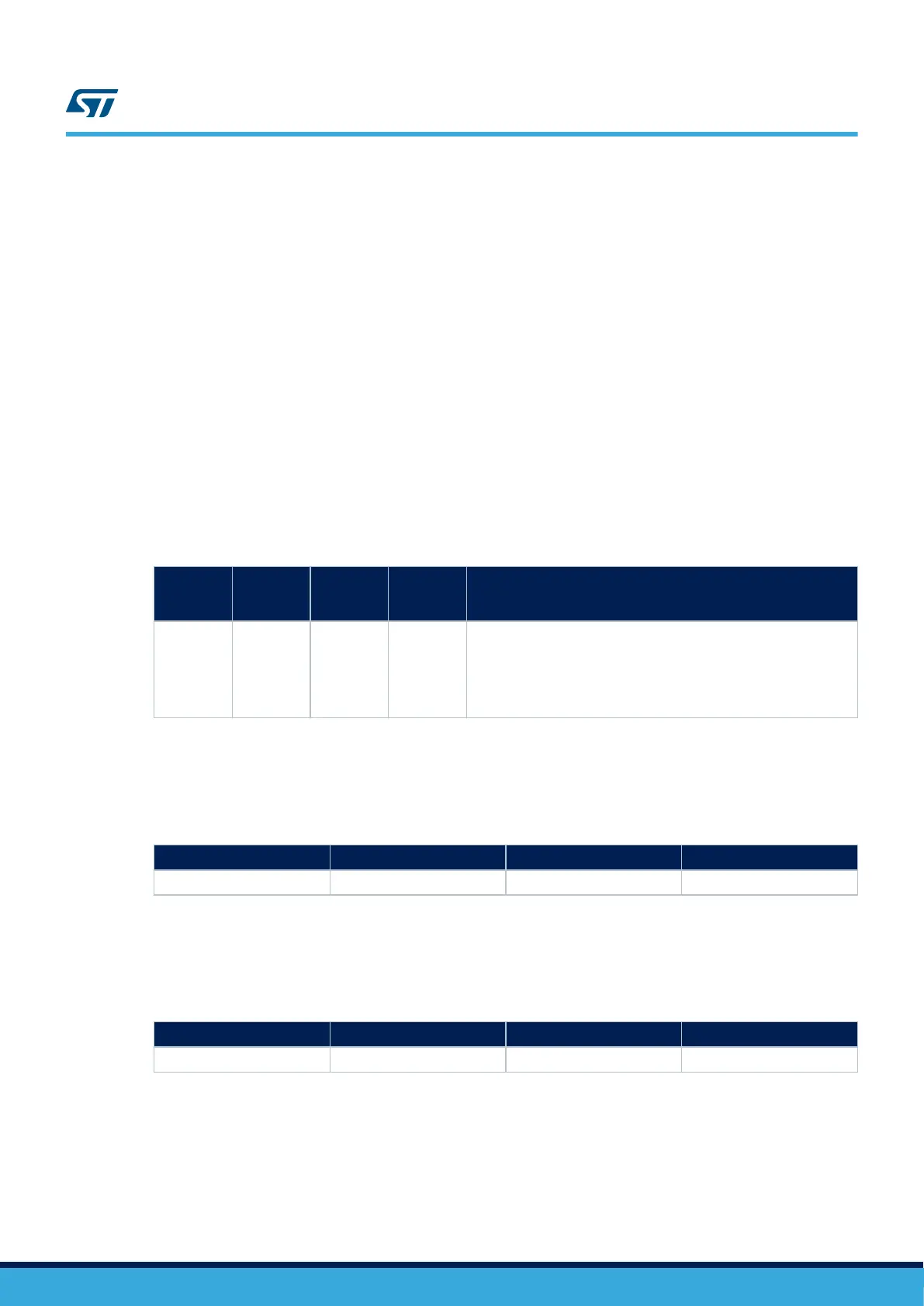
Table 5. External power sources: VIN (7 to 12 V)
Input
power
name
Connector
pins
Voltage
range
Maximum
current
Limitation
VIN CN19 pin 8 7 to 12 V 800 mA
From 7 V to 12 V only and input current capability is linked to input
voltage:
• 800 mA input current when VIN = 7 V
• 450 mA input current when 7 V < VIN < 9 V
• 250 mA input current when 9 V < VIN < 12 V
8.2.3 Supplying the STM32H7B3I-DK using USB charger (5 V)
When the STM32H7B3I-DK board is power supplied by a USB charger through CN14 (see Table 6), the jumper
must be placed on pin 9-10 of JP1 “CHGR”.
Table 6. External power source: CHGR (5 V)
Input power name Connector pins Voltage range Maximum current
CHGR CN14 5 V -
8.2.4 Supplying the STM32H7B3I-DK using USB OTG HS connector (5 V / 500 mA)
When the STM32H7B3I-DK board is power supplied by the host PC through the CN15 USB OTG HS connector
(see Table 7), the jumper must be placed on pin 5-6 of JP1 “U5V”.
Table 7. External power source: U5V (5 V)
Input power name Connector pins Voltage range Maximum current
U5V CN15 5 V -
UM2569
Power supply
UM2569 - Rev 1
page 15/54

 Loading...


