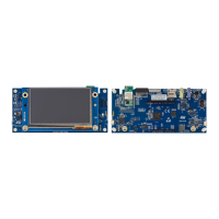
B.2 ESP-01 Wi‑Fi
®
board compatible connector
The ESP-01 Wi‑Fi
®
board connector is 2.54"-pitch with 2x4-pin female connectors. Table 28 shows the definition
of the pins.
Table 28. Description of the ESP-01 Wi‑Fi
®
connector pins
STMod+ connector number ESP-01 function
Pin
number
Pin
number
ESP-01 function STMod+ connector number
STMod+#5#16 GND GND 1 8 TXD STMod+#3-RX
STMod+#14 GPIO2 2 7 CH_PD STMod+#13
STMod+#11 GPIO0 3 6 RST STMod+#12-RST
STMod+#2-TX RXD 4 5 VCC -
B.3 Compatible connectors for the Grove boards
The two connectors of the Grove board are 2.54"-pitch with 1x4-pin male connectors. The part number is 1125S-
SMT-4P.
Warning:
On MB1280 revision A and B PCBs, the I
2
C interface is only 3.3 V tolerant. For the 5 V Grove
module, a fanout MB1280 revision C PCB is mandatory.
B.3.1 Compatible connectors for I
2
C Grove boards (Fanout CN3)
The CN3 connector is compatible with the Grove barometer sensor (BMP180) and the Grove LCD RGB backlight
boards using a cable for connection. Table 29 shows the definition of the pins.
Table 29. Description of the I
2
C Grove board CN3 connector pins
STMod+ connector pin CN3 Grove function Pin number
STMod+#7-SCL (*) SCL 1
STMod+#10-SDA (*) SDA 2
+5 V VCC 3
- GND 4
B.3.2 Compatible connector for UART Grove boards (Fanout CN2)
The CN2 connector is compatible with Grove NFC boards using a cable for connection. Table 30 shows the
definition of the pins.
Table 30. Description of the UART Grove board CN2 connector pins
STMod+ connector number CN2 Grove function Pin number
STMod+#3-RX RX (Grove TX) 1
STMod+#2-TX TX (Grove RX) 2
+5 V VCC 3
- GND 4
UM2569
ESP-01 Wi‑Fi® board compatible connector
UM2569 - Rev 1
page 43/54

 Loading...