9.4 P1 STMod+ connector
The standard 20-pin STMod+ connector is available on the STM32H7B3I-DK board to increase compatibility with
external boards and modules from the Ecosystem of microcontrollers. By default, it is designed to support an ST-
dedicated fanout board to connect different modules or board extensions from different manufacturers.
For more detailed information, refer to Section Appendix B .
For details about STMod+ interface, refer to the technical note STMod+ interface specification (TN1238).
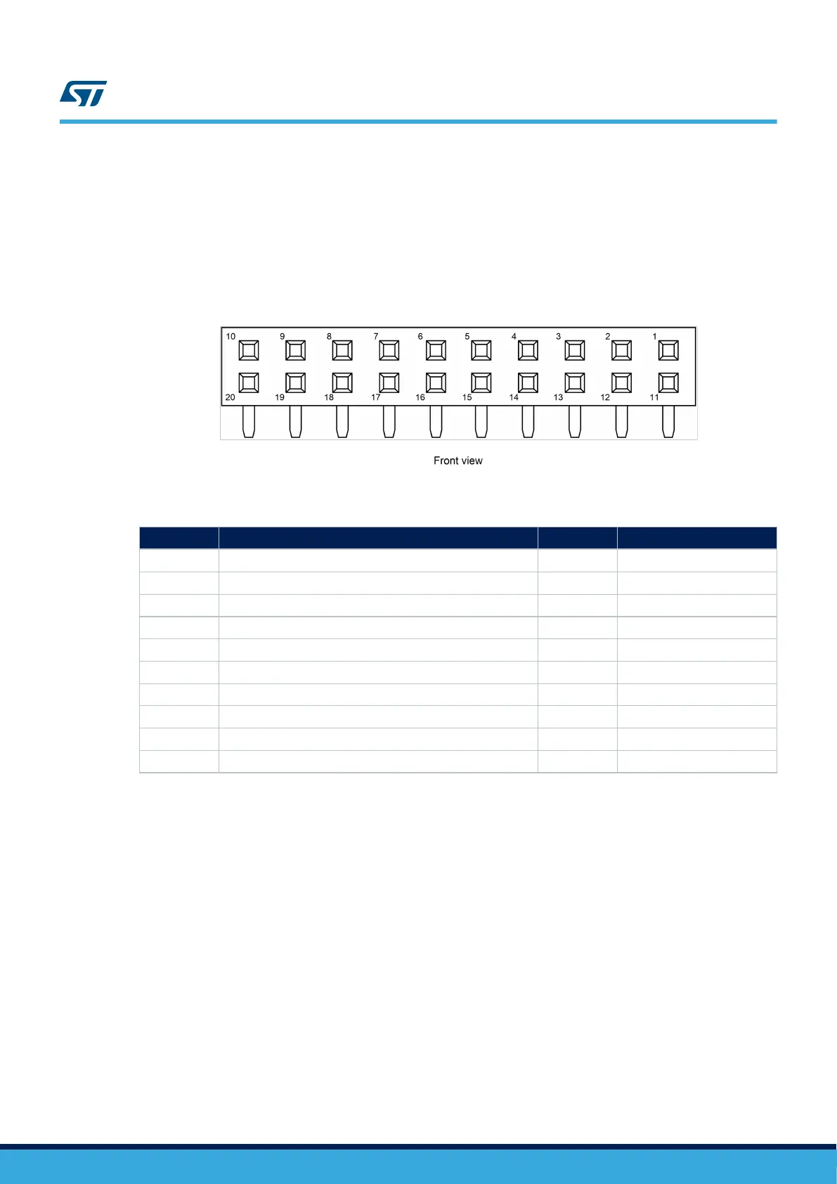
Figure 19. P1 STMod+ connector
Table 15. P1 STMod+ connector pinout
Pin number Description Pin number Description
1 SPI2_NSS / USART2_CTS (PA11/PA0) 11 INT (PC6)
2 SPI2_MOSI / USART2_TX (PC3/PD5) 12 RESET (PH8)
3 SPI2_MISO / USART2_RX (PC2/PD6) 13 ADC (PA4)
4 SPI2_SCK / USART2_RTS (PA12/PD4) 14 PWM (PF8)
5 GND 15 5V
6 5V 16 GND
7 I2C4_SCL (PD12) 17 DFSDM-DATA3 (PC7)
8 SPI2_MOSIs (PB15) 18 DFSDM-CKOUT (PD3)
9 SPI2_MISOs (PB14) 19 DFSDM-DATA7 (PB9)
10 I2C4_SDA (PD13) 20 DFSDM-CK7 (PB8)
Note: Note that this connector shares many GPIOs with other functions on the boards. For more detailed information,
refer to Section Appendix A STM32H7B3I-DK I/O assignment. In addition, to have a quick look at STMod+
GPIO sharing and multiplexing, and to get a quick view on other alternate functions available on its pins, refer to
Section Appendix C STMod+ GPIO sharing and multiplexing.
UM2569
P1 STMod+ connector
UM2569 - Rev 1
page 28/54