9.5 CN7 camera module connector
On the STM32H7B3I-DK board, a 30-pin CN7 connector with Digital Camera Interface DCMI signals is available
to connect an 8-bit camera module such as the STM32F4DIS-CAM module. This module must be connected with
caution before powering the STM32H7B3I-DK board.
Note:
The camera clock is the MCO clock by default. I
2
C address for the STM32F4DIS-CAM module is 60h and 61h.
Limitations:
Care must be taken of GPIO sharing and multiplexing with other functions, in order to program the good
configuration. GPIO assignment and sharing are precise below:
•
DCMI_SDA and DCMI_SCL I
2
C peripheral share with STMod+ connector, ARDUINO
®
connector, audio
codec, and TFT LCD.
• Camera signals PA4, PB8, PB9, PC6, PC7, and PD3 are shared with STMod+ connector.
• Camera signals PC9 and PC11 share with SDIO1_D1 and SDIO1_D3 signals
•
DCMI_HSYNC camera signal (PA4) shares with ARDUINO
®
ARD_A0 signal.
As a consequence, when using the camera, the user must pay attention that there is nothing connected to STMod
+ connector. And SB44 must be OFF. Same, when using the camera, the microSD
™
cannot be used.
At least, the user must take care that the SB45 is OFF (ARD_A0 signal disconnected to PA4).
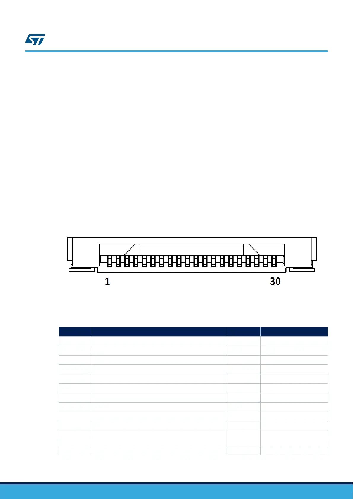
Figure 20. CN7 camera module connector
Table 16. CN7 camera module connector pinout
Pin number
Description Pin number Description
1 GND 16 GND
2 NC 17 DCMI_HSYNC (PA4)
3 NC 18 NC
4 DCMI_D0 (PC6) 19 DCMI_VSYNC (PB7)
5 DCMI_D1 (PC7) 20 VDD (3V3)
6 DCMI_D2 (PG10) 21 CAMERA_CLK (MCO1) (PA8)
7 DCMI_D3 (PC9) 22 NC
8 DCMI_D4 (PC11) 23 GND
9 DCMI_D5 (PD3) 24 NC
10 DCMI_D6 (PB8) 25 DCMI_PWR_EN (PA7)
11 DCMI_D7 (PB9) 26
DCMI_NRST (NRST from
MCU)
12 NC 27 I2C4_SDA (PD13)
UM2569
CN7 camera module connector
UM2569 - Rev 1
page 29/54