8.6.9 Virtual COM port
The serial interface USART1 (PA9/PA10), which supports the bootloader, is directly available as a Virtual COM
port of a PC connected to the CN14 STLINK-V3E USB connector. The VCP configuration is the following:
• 115200 bit/s
• 8-bit data
• No parity
• 1 stop bit
• No flow control
8.6.10 TAG
A CN12 TAG interface footprint is reserved on the STM32H7B3I-DK board, which can be used to debug and
program the board.
8.6.11 Buttons and LEDs
The black button B1 located on the top side is the reset of the STM32H7B3LIH6QU microcontroller.
The blue button B2 located on the top side can be used as a digital input or as a wakeup-alternate function.
When the button is depressed the logic state is LOW, otherwise, the logic state is HIGH.
Two LEDs located on the top side, blue LD2 and red LD3, are available for the user. To light a LED, a logic state
HIGH must be written in the corresponding GPIO register. Table 10 shows the assignment of the control ports to
the LED indicators.
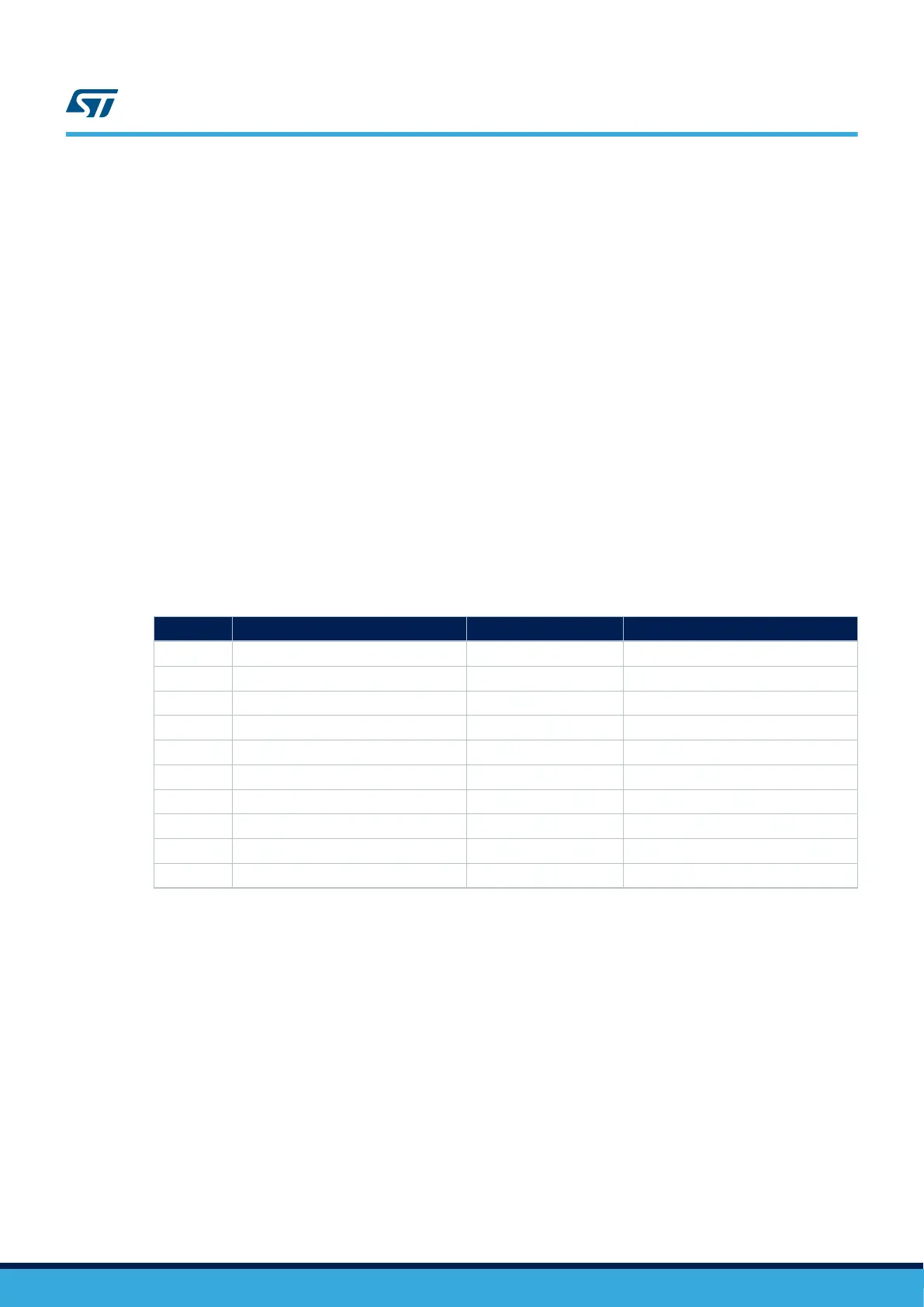
Table 10. Button and LED control port
Reference Color Name Comment
B1 Black Reset -
B2 Blue Wake-up Wake-up alternate function
LD1 Green LED1 PA12 alternate with ARD D13
LD2 Blue LED2 PG2 user LED2
LD3 Red LED3 PG11 user LED1
LD4 Bicolor red and green ST-LINK COM Green during communication
LD5 Green 5 V power 5 V available
LD6 Green VBUSOK USB 5 V available
LD7 Red Power fault Current higher than 550 mA
LD8 Red VBUS OCRCR PH12
UM2569
Board functions
UM2569 - Rev 1
page 22/54
 Loading...


