9 Board connectors
16 connectors are implemented on the STM32H7B3I-DK board.
• CN14: STLINK-V3E USB Micro-B
• CN15: USB OTG HS Micro-AB
• CN4: microSD
™
• P1: STMod+
• CN7: Camera
• CN12: TAG
•
CN16: External I
2
C
• CN3: Audio extension board (DFSDM)
• CN8: STDC14/MIPI10
•
CN10, CN11, CN19, and CN20: ARDUINO
®
Uno Revision 3
• CN1: LCD
• CN5 and CN6: Audio jack
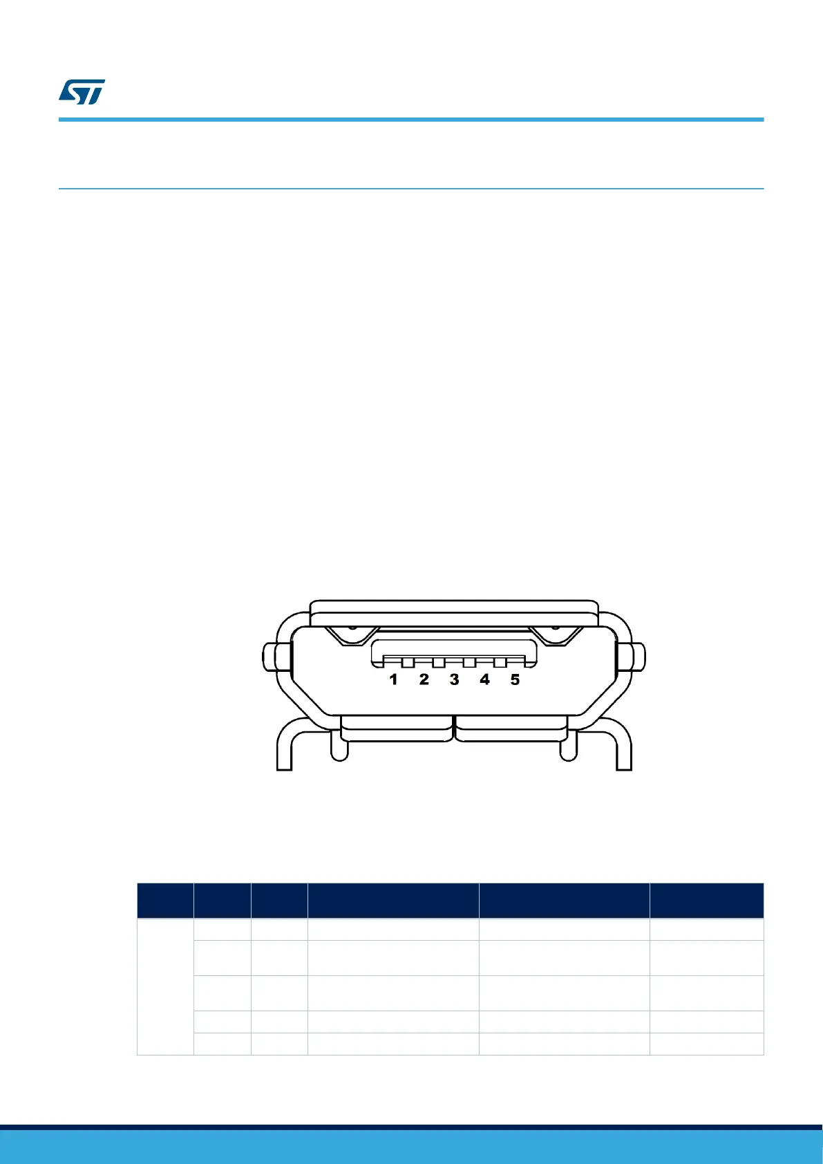
9.1 CN14 STLINK-V3E USB Micro-B connector
The CN14 USB connector is used to connect the embedded STLINK-V3E to the PC for programming and
debugging purposes.
Figure 16. CN14 Micro-B connector (Front view)
The related pinout for the USB ST-LINK connector is listed in Table 12.
Table 12. CN14 USB Micro-B connector pinout
Connect
or
Pin
number
Pin
name
Signal name ST-LINK MCU pin Function
CN14
1 VBUS 5V_USB_CHARGER - 5 V power
2 DM USB_DEV_HS_CN_N PB14
USB differential pair
M
3 DP USB_DEV_HS_CN_P PB15
USB differential pair
P
4 ID - - -
5 GND - - GND
UM2569
Board connectors
UM2569 - Rev 1
page 25/54