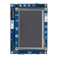
7.22 Buttons and LEDs
The black button (B1) on the top side is the reset of the STM32N657X0H3Q microcontroller.
The blue button (B2) on the top side is used as the user1 button (wake-up-alternate function).
The blue button (B4) on the top side is used as a tamper button.
When the black button (B1) is pressed, the logic state is LOW, otherwise, the logic state is HIGH.
The LD2 LED might be used for BOOTFAILEDN signal with LED for boot ROM failure detection.
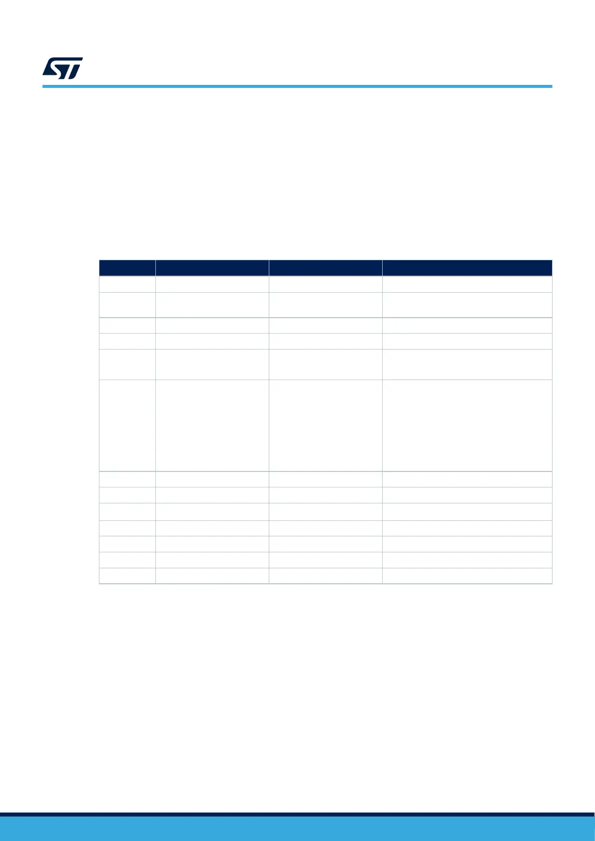
Table 8 summarizes the different buttons and LEDs of the STM32N6570-DK Discovery kit and their function:
Table 8. Button and LED control ports
Reference Color Function Description
B1 Black Reset button Resets the board.
B2 Blue User1 button
Supports the wake-up and tamper features
(PC13).
B4 Blue Tamper button PE0
LD1 Green User LED Active HIGH (PO1)
LD2 Red User LED
Active LOW (PG10)
(Might indicate BOOTFAILEDN)
LD3 Tricolor (orange/green/red) STLINK-V3EC power status
Power status:
(1)
• OFF: Target not powered by ST-LINK
• Orange: Requested power higher than
USB power budget
• Green: Requested power lower or
equal to USB power budget
• Red: Overcurrent detected
• Blinking red: Internal error
LD4 Bicolor (red/green) STLINK-V3EC COM Green when communication is ongoing
LD5 Green User 5 V 5 V ON
LD6 Green
ARDUINO
®
D13
Active HIGH (PE15)
LD7 Green Ethernet LED2 Ethernet status
LD8 Red USB2 FAULT USB2 fault
LD9 Green USB1 5V VBUS1 is present
LD10 Red USB1 OVP It indicates USB1 OVP status.
1. For detailed information on the power status LED, refer to the technical note Overview of ST-LINK derivatives (TN1235),
section 7.
UM3300
Hardware layout and configuration
UM3300 - Rev 1
page 20/49