8.4 STMod+ connector (CN4)
The standard 20-pin STMod+ connector is available on the STM32N6570-DK board to increase compatibility with
external boards and modules from the ecosystem of microcontrollers. STMod+ includes UART or SPI interface
signals for communication with the host MCU and the dedicated solder bridges allow configuring the external
board to be controlled by the UART2 or SPI5 serial interface of the STM32N657X0 MCU.
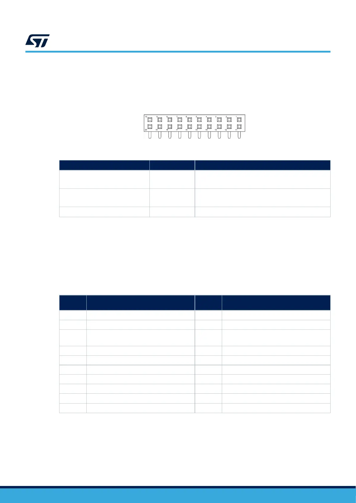
Figure 15. STMod+ connector (CN4) front view
Table 12. STMod+ connector (CN4) configuration
Solder bridge
Setting
(1)
Description
SB10, SB12, SB14, SB17
SB11, SB13, SB15, SB18
ON
OFF
UART2 connected to STMod+
SPI5 disconnected to STMod+
SB10, SB12, SB14, SB17
SB11, SB13, SB15, SB18
OFF
ON
UART7 disconnected to STMod+
SPI5 connected to STMod+
SB16 ON
SB16 ON to enable the ADC (Share ARDUINO
®
A5)
1. The default configuration is in bold.
By default, it is designed to support an ST-dedicated fan-out board to connect different modules or board
extensions from different manufacturers.
The STMod+ fan-out expansion board also embeds a 3.3 V regulator and I
2
C level shifters. For more detailed
information on the fan-out board, refer to the user manual STMod+ fan-out expansion board for STM32 Discovery
kits and Evaluation boards (UM2695).
For details about the STMod+ interface, refer to the technical note STMod+ interface specification (TN1238).
Table 13. STMod+ connector (CN4) pinout
Pin
number
Description
Pin
number
Description
1 SPI5_CS (PA3)/USART2_CTS (PG5) 11 INT (PC11)
2 SPI5_MOSI (PG2)/USART2_TX (PD5) 12 RESET (PB3)
3 SPI5_MISO (PH8)/USART2_RX (PF6) 13
ADC (PB10) (share ARDUINO
®
A5) or I/O(PC9)
(1)(2)
4 SPI5_SCK (PE15)/USART2_RTS (PG14) 14 PWM (PC7)
5 GND 15 +5 V
6 +5 V 16 GND
7 I2C1_SCL (PH9) 17 GPIO (PD13)
8 SPI5_MOSIs (PH7) 18 GPIO (PF1)
9
I/O (PC6) (missing MISO signal)
(3)
19 GPIO (PB8)
10 I2C1_SDA (PC1) 20 GPIO (PG9)
1. Since for ADC, the level of MCU is 1.8 V, while for digital I/O the level of MCU pins is 3.3 V.
2.
STMod+ shares the same ADC (CN4 pin13) with ARDUINO
®
ADC5 (A5).
3. Losing one SPI for CN4 pin9 due to no spare SPI resource.
Note:
On the STM32N6570-DK board, signals on STMod+ are shared with ARDUINO
®
connectors. The user must
make sure that nothing is connected to
ARDUINO
®
connectors.
UM3300
Board connectors
UM3300 - Rev 1
page 23/49