8.9
microSD
™
card connector (CN13)
microSD
™
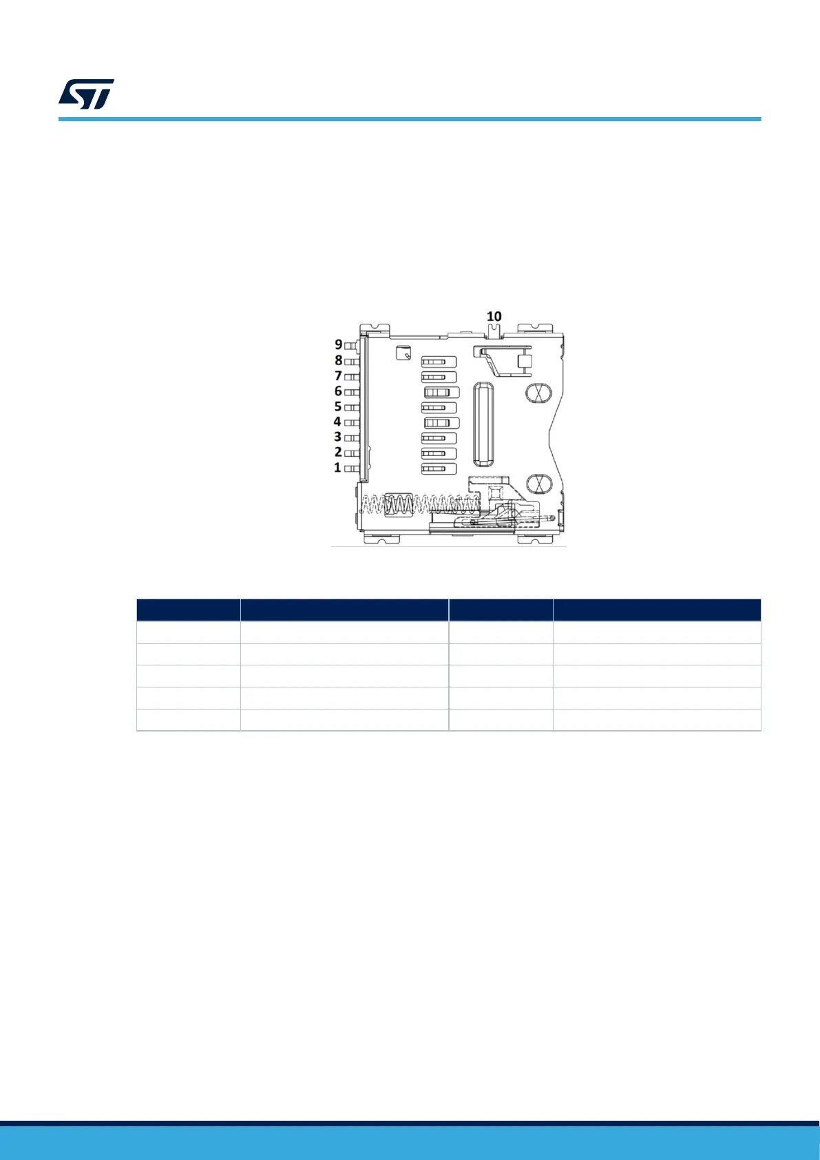
cards with 4 Gbytes or more capacity can be inserted in the receptacle (CN13). Four data bits of the
SDMMC2 interface, CLK, and CMD signals of the STM32N657X0H3Q are used to communicate with the
microSD
™
card. The SD_Detect signal detects the card insertion. When a microSD
™
card is inserted, the
SD_Detect level is LOW, otherwise, it is HIGH.
Note: There are also some control signals to manage the power of the SD card: SD_SEL (PO5), PWR_SD_EN (PQ7),
and NRST.
Figure 19. microSD
™
connector (CN13) top view
Table 18. microSD
™
connector (CN13) pinout
Pin number
Description Pin number Description
1 SDMMC2_D2 (PC0) 6 GND
2 SDMMC2_D3 (PE4) 7 SDMMC2_D0 (PC4)
3 SDMMC2_CMD (PC3) 8 SDMMC2_D1 (PC5)
4 VDD_SD 9 GND
5 SDMMC2_CK (PC2) 10 SD_Detect (PN12)
UM3300
Board connectors
UM3300 - Rev 1
page 28/49