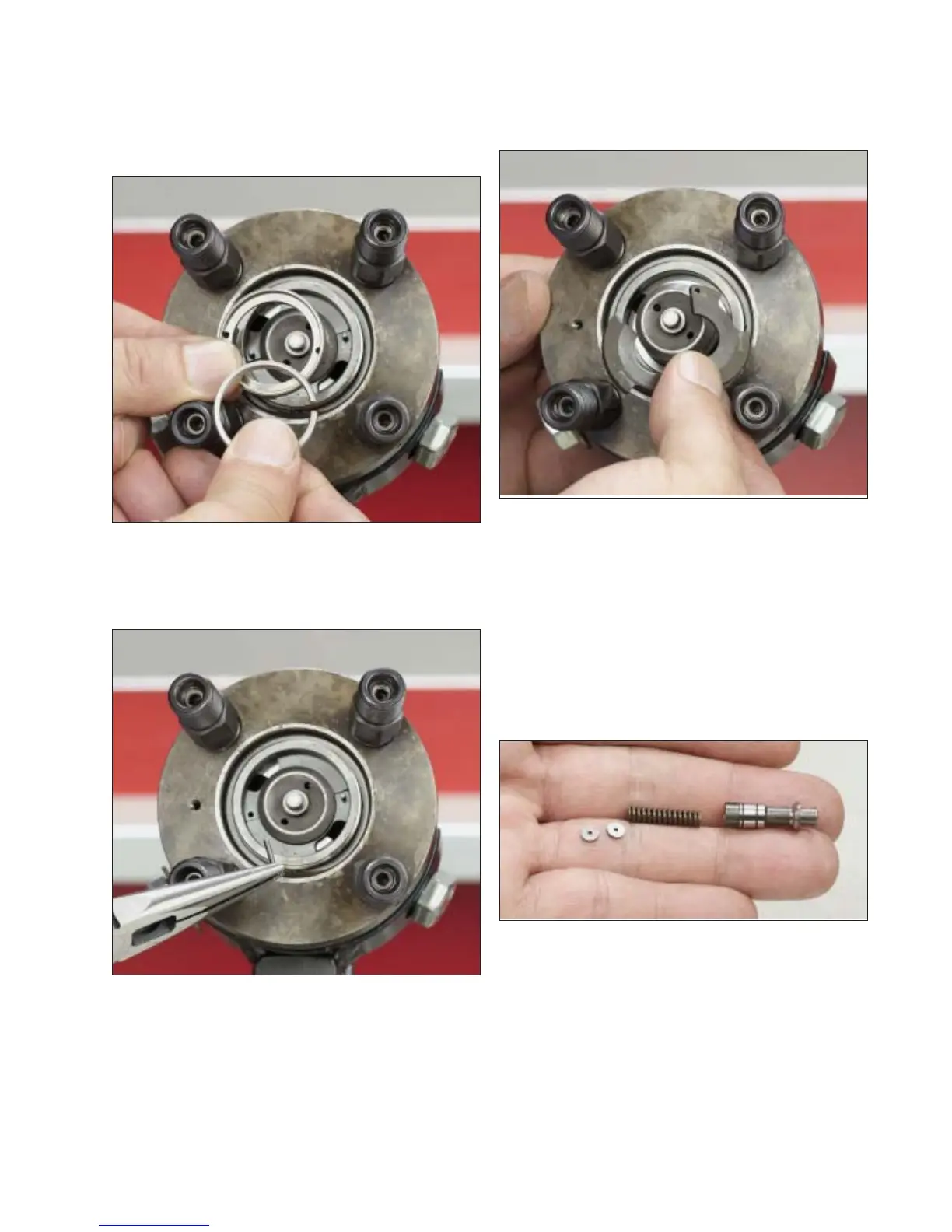
Step 39 Remove the adjustable spacer re-
tainer and adjustable spacer (crush washer)
from the hydraulic head. Discard the adjustable
spacer.
Step 40 Remove the 2 rotor retainer locating
pins using long nose pliers.
Step 41 Push up on the end of the rotor from
beneath the fixture while removing the 2 rotor
retainers, then pull the rotor through the hydrau-
lic head assembly to remove. Hold the rotor
carefully at the ends so as not to handle finely
Fig. 2-39
finished surfaces.
Step 42 Remove poppet valve, poppet valve
spring and poppet valve shims. Measure and
record thickness of the shims. If shims are mis-
placed, it will be necessary to replace them with
shims of the exact same thickness. Refer to
Parts Inspection section and the individual
specification for information on replacement
shims.
Step 43 Loosen and remove the 4 snubber
plate retaining screws using a 1/8” hex bit
Fig. 2-40
Fig. 2-41
Fig. 2-42
22