Step 16 Install the thrust washer with the cut-
out over the roll pin.
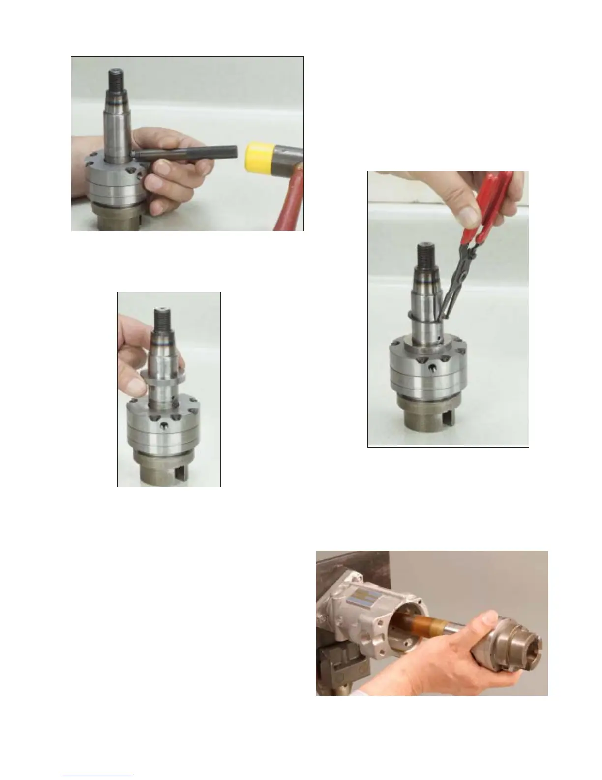
Step 17 Orient the transfer pump assembly
group retaining ring with the sharp edge facing
upwards. Using retaining ring pliers 20044, ex-
pand the retaining ring and carefully slide it down
the shaft into its groove. NOTE: Exercise ex-
treme care not to allow contact possibly
scratching the drive shaft in the area where the
seals ride.
Step 18 Using the protection tube, 36272 on
the end of the drive shaft slide the drive shaft/
transfer pump assembly into the housing and
align the transfer pump porting plate screw hole
with the hole in the housing.
Fig. 4.15
Fig. 4.16
Fig. 4.17
Fig. 4.18
32