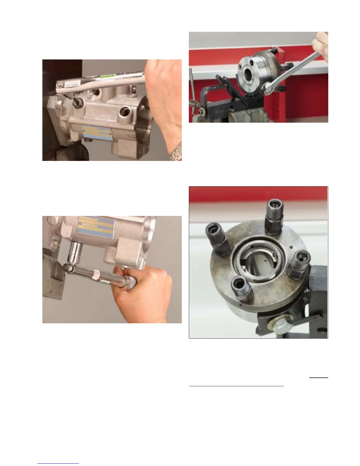
Step 22 Install the transfer pump porting plate
screw and tighten to 140–160 lbf-inches (16.0-
18 N-m) using a 3/16” hex bit.
Step 23 Using a 1/2” socket, tighten the port-
ing plate locking screw on the underside of the
pump to 220-240 lbf-inches (25-27N-m).
Step 24 Remove the dial indicator from the
31204 poppet valve gap setting fixture and
clamp fixture in vise. Mount hydraulic head in
the fixture using the two provided bolts – one in
the head locating screw and the other in the
head locking screw hole. Reorient head and fix-
ture in the vise so that the fuel line connectors
are facing upwards.
34
Fig. 4.22
Fig. 4.23
Step 26 Holding the rotor at the end, not by
the finely finished center section, rinse the rotor
in clean calibrating fluid. Lower the rotor, plunger
end first, into the hydraulic head assembly.
NOTE: Do not attempt to insert the rotor into
the head, poppet valve end first. Then, while
supporting the rotor from beneath with one fin-
Fig. 4.24
Fig. 4.25
Step 25 Insert the two rotor retainer locating
pins into the head assembly.