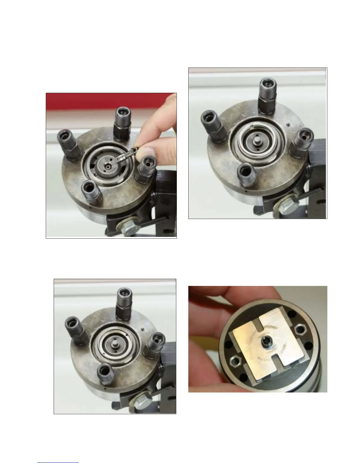
Step 30 Install poppet valve, notched end
down, into its bore in the rotor, making sure to
engage the notch in the valve with the cross pin
in the bore. If necessary refer to the Parts In-
spection Section and the individual specifica-
tion for information on poppet valve replace-
ment.
Step 31 Install the adjustable spacer retainer,
notches down, onto the head assembly with the
holes engaging the rotor locating pins.
36
Fig. 4.30
Fig. 4.31
Step 32 Install a new adjustable spacer (crush
washer) into the counterbore of the adjustable
spacer retainer. Radial location of the opening
in the spacer is unimportant.
Step 33 Assemble two new seals to the fuel
control solenoid body and insert the armature
pin assembly into the solenoid body. NOTE:
alignment of the notches in the pin assembly to
the terminal stud holes in the solenoid body.
Fig. 4.32
Fig. 4.33