Step 41 Using the 30853 armature cover
spanner wrench slowly begin rotating the sole-
noid assembly clockwise as viewed from the
fuel line connector end of the hydraulic head to
tighten the solenoid down against the adjust-
able spacer (crush washer).
39
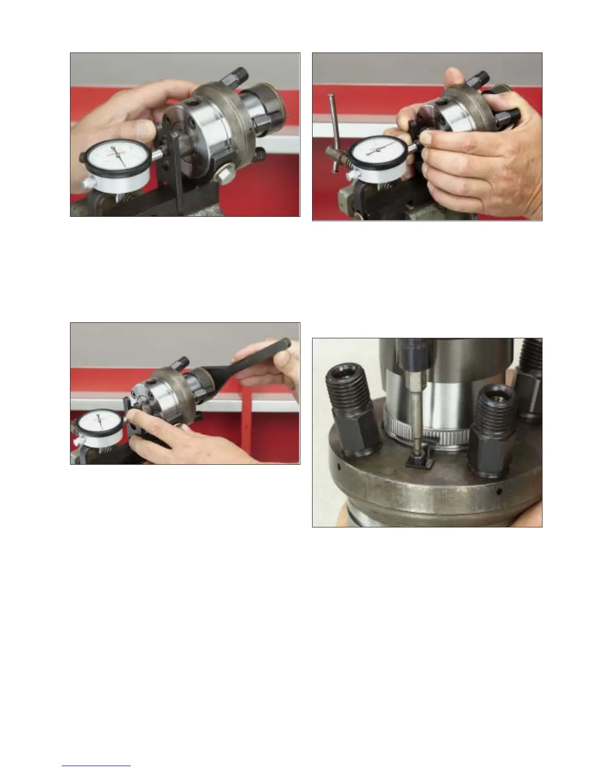
Fig. 4.40
Step 42 While tightening the solenoid, re-
peatedly deflect the rotor in and out of the
hydraulic head using the lever on the fixture
and observe the dial indicator reading. Con-
tinue to tighten the solenoid to reduce the dial
indicator reading until the specified poppet
valve lift is attained. (Refer to the individual
specification) NOTE: Never back out the so-
lenoid to attain the correct lift. If the solenoid
is rotated too far and a poppet valve lift below
specification results, the solenoid will have to
be removed and a new adjustable spacer in-
stalled and the setting procedure repeated.
Step 43 Install the fuel control solenoid lock-
ing plate and retaining screw to the hydraulic
head. Tighten screw to 15-18 lbf-inches (1.7-2
N-m) using a T-10 bit.
Step 44 Install the two pumping plungers into
the plunger bores in the rotor.
Fig. 4.41
Fig. 4.42
Fig. 4.43