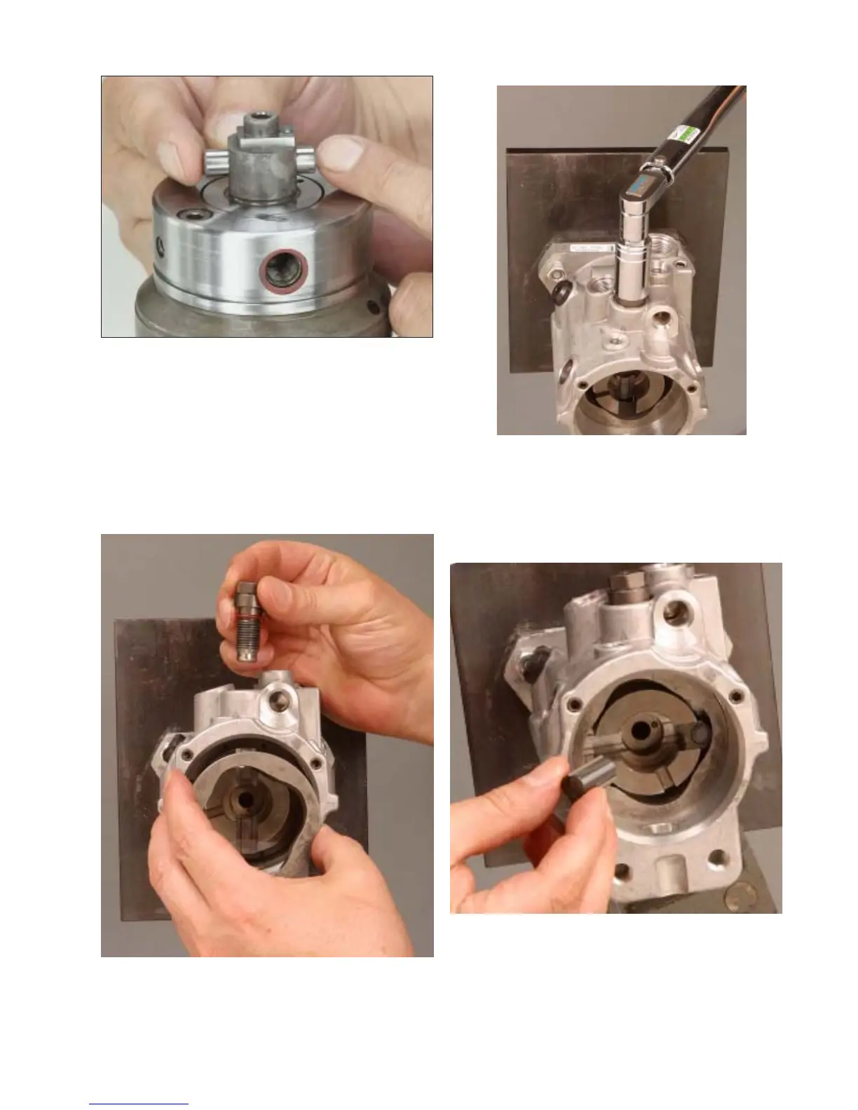
Step 45 Tilt vise so that the drive shaft is
pointing straight down. Install the cam ring, ar-
row side up, into the housing and position with
the cam locating screw hole facing the top of
the pump. Install the cam locating screw into the
hole in the housing and tighten to 880-920 lbf-
inches (99-104 N-m)
40
Fig. 4.44
Fig. 4.45a
Fig. 4.45b
Fig. 4.46
Step 46 Assemble the rollers to the cam
shoes and install them into the slots in the drive
shaft. Make sure that the cam rollers/shoes re-
main in contact with the cam ring.