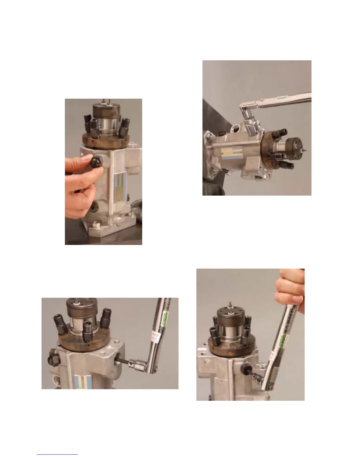
Step 50 Assemble two new seals to both
head locking screws and lubricate with
Lubriplate grease. Install the screw which incor-
porates the transfer tap and has a 3/4” hex head
to the transfer pump regulator side of the pump
finger tight. Install the remaining head locking
screw to the opposite side of the pump finger
tight.
Step 51 Tighten the head locating screw on
the bottom of the pump to 180-220 lbf-inches
(20-25 N-m) using a 3/16” hex bit.
42
Fig. 4.51
Fig. 4.50
Step 52 Tighten the head locking screw on
the regulator side to 180-220 lbf-inches (20-25
N-m) using a 3/4” socket.
Step 53 Tighten the remaining head locking
screw using a 3/16” hex bit to 180-220 lbf-inches
(20-25 N-m).
Fig. 4.52
Fig. 4.53