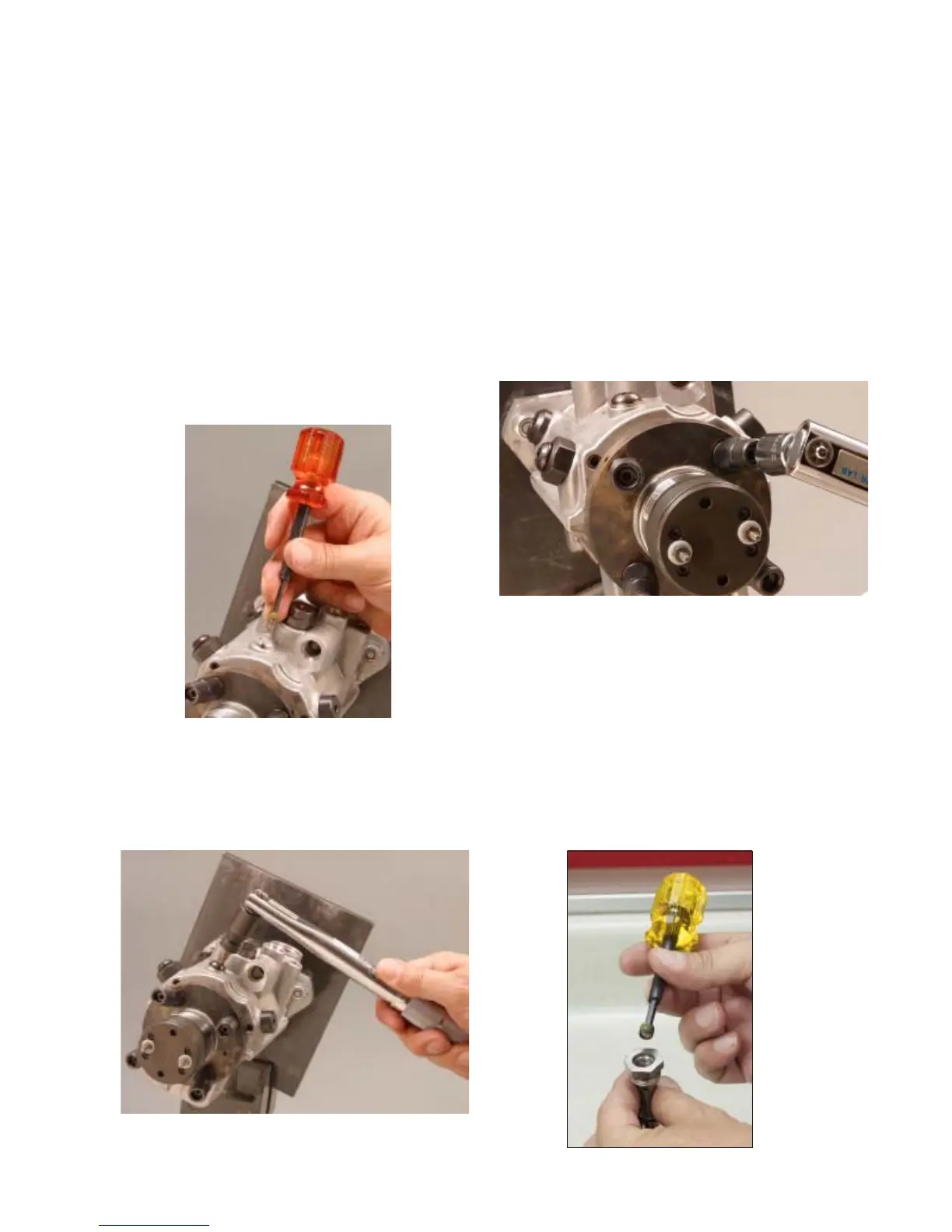
Step 54 Install the vent wire assembly into the
hydraulic head. Tighten to 25-30 lbf-inches (3-
3.5 N-m) using a 1/8” hex bit. Five different vent
wire assemblies are available to control the
volume of return oil flow from the pump. Refer
to the individual specification for part numbers.
During reassembly it is recommended to rein-
stall the same vent wire that was removed dur-
ing disassembly and then during calibration a
different number wire can be installed as nec-
essary to achieve the specified return fuel flow.
Vent wire assemblies are marked with numbers
0 – 5 on the ends to identify them. The higher
the number the less fuel flow through the vent
wire assembly.
Step 55 Assemble a new sealing washer to
the vent wire assembly access screw. Install the
screw into the housing and tighten to 60-70 lbf-
inches (7-8 N-m) using a T40IPR bit.
Step 56 Install a new seal on the transfer
pump tap screw and install the plug into the head
locking screw hand tight. The screw will be tight-
ened to 110-130 lbf-inches (12.5-15 N-m) us-
ing a T40 bit during calibration.
Step 57 Install the snubber plates and springs
into all the fuel line connectors.
Step 58 Dip the snubber valve retaining
screws in clean calibrating fluid and install one
in each fuel line connector. Tighten each screw
to 40-60 lbf-inches (4.5-6.8 N-m) using a 1/8”
hex bit.
Step 59 Insert the transfer pump regulator pis-
ton, spring and adjusting plug into the transfer
pump regulator assembly. Thread the adjusting
plug until the top of the plug is just below the fuel
flow passages. NOTE: It may be necessary to
hold the regulator assembly in a vise by its
hex head in order to install the screw due to
the thread locking compound on the plug.
43
Fig. 4.54
Fig. 4.55
Fig. 4.58
Fig. 4.59