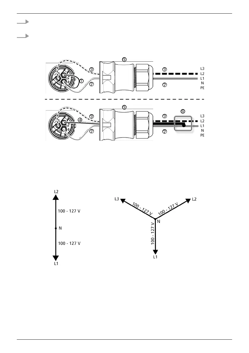
1. Wire the AC plug supplied to match the selected external conductors, as described in the
Appendix under Mounting ⇒ AC plugs. Do not yet close the AC plug.
2. Connect one of the two connected phases to PE at the inverter side. Make this connection
inside the AC plug or use an external junction box, as shown in
Fig. 12.
Fig. 12: Connection of N and PE in the AC plug (above) or junction box (below)
①
Connection cable between N and PE with the connection point inside the AC plug
②
External conductor L1
③
External conductor L2
④
Connection cable between N and PE with the connection point inside the junction box
⑤
Casing of the AC plug
⑥
Junction box
Fig. 13: External conductor voltages in 2- and 3-phase grids with 100 V ... 127 V
EN
747,431 | Z09 | 2015-09-30
38