47
742.221 | 12.04
EN
6.3.4 Abbreviations
Abbreviation Description
MSD internal grid monitoring of the inverter (MSD = Mains monitoring with allocated
Switching Devices)
MPP working point producing the most power (Maximum Power Point)
SELV Safety Extra Low Voltage
V
PV
The generator voltage present at the DC connection (photovoltaic voltage)
Tab. 5: Abbreviations
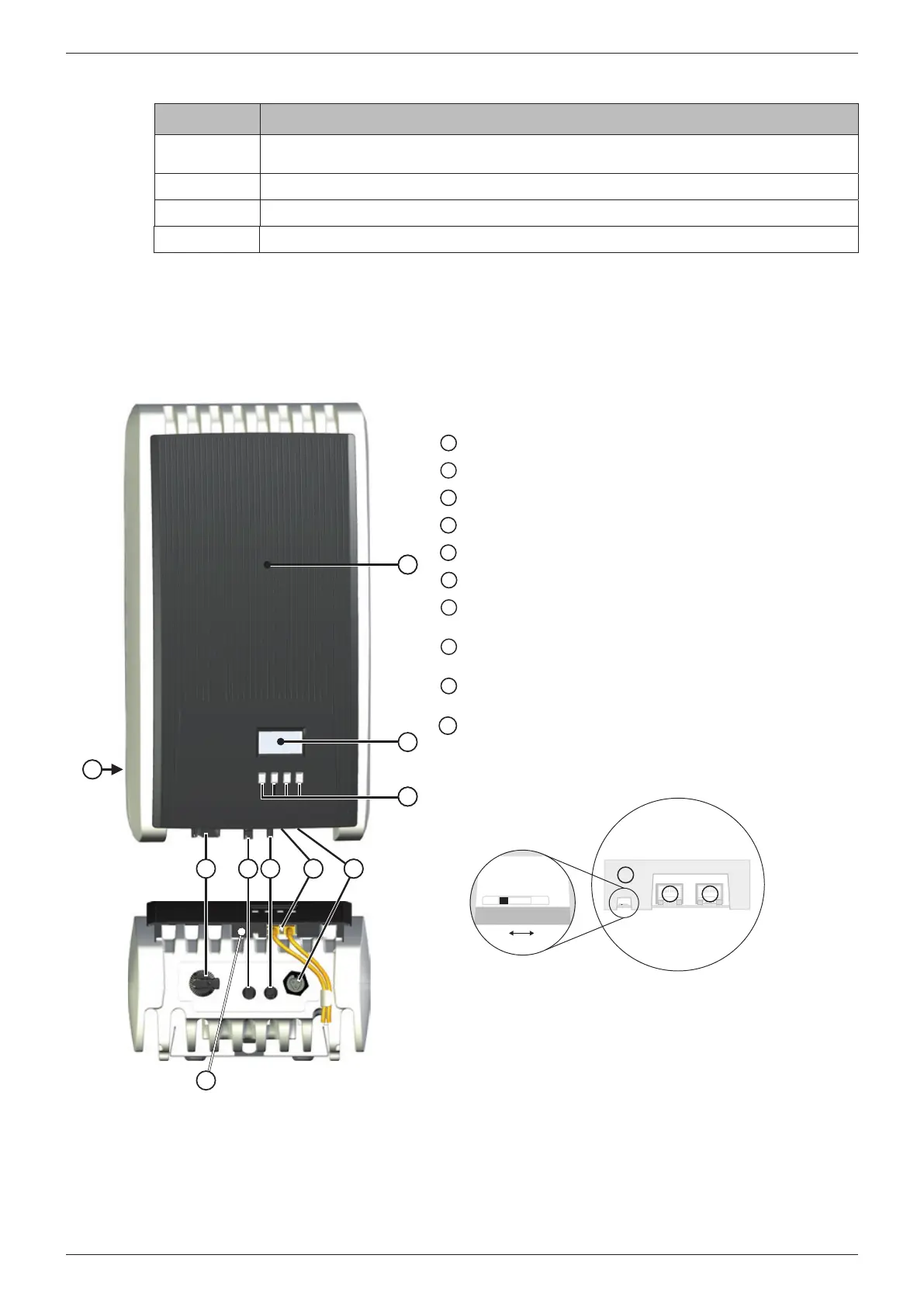
7 Structure and function
7.1 Casing
16
9
1
8
7 15
11
2
3
14
10
Hood
Display (monochrome, 128 x 64 pixels)
13
Type plate, Warning notices
14
Operating buttons: ESC, , , SET (from left to right)
15
1 AC connection
16
2 RJ45 sockets (RS485 interface)
1 minus DC connection (–) for solar modules (Multi-
contact MC4 DC socket, contact proof)
8
1 plus DC connection (+) for solar modules (Multi-
contact MC4 DC socket, contact proof)
19
DC circuit breaker (interrupts the plus and minus in-
puts simultaneously)
10
Termination (slide switch):
On: termination switched on (slide switch at the right)
Off: termination switched off (slide switch at the left)
See also the detail drawing below.
Off
On
66
10
Fig. 5: Components on the front and lower sides of the casing
The individual casing components are described in detail below.