54
742.221 | 12.04
EN
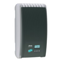
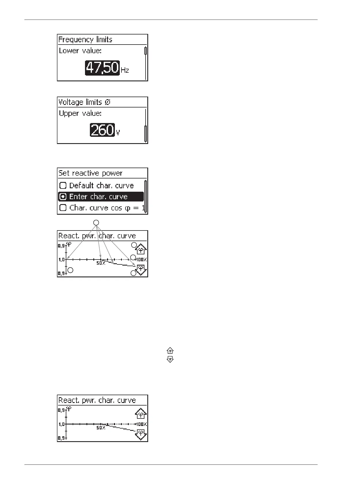
Frequency limits
The following frequency limits can be changed:
• Upper frequency disconnection value
• Lower frequency disconnection value (fig. left)
• Derating switch-on threshold (because frequency is too high)
• Frequency threshold when switching on again
Voltage limits ø (average value)
The following voltage limits can be changed:
• Upper voltage disconnection value
1)
(fig. left)
• Lower voltage disconnection value
1)
1)
The disconnection value relates to the average value of
the voltage.
React. pwr. char. curve
Overview
4
5
2
2
3
1
The reactive power characteristic curve must be set during
initial commissioning if this is prescribed for the previously
selected country. The following applies:
• 3 characteristic curves are available for selection (fig. left):
– Default. char. curve (pre-defined)
– Char. curve cos φ = 1 (pre-defined)
– Enter char. curve (manually adjustable)
• After configuration, the characteristic curve is displayed as
a graph (example in fig. left).
x-axis, output power P in %
y-axis, phase shift cos φ
Nodes (in example: 4 nodes)
Arrow symbol Overexcitation
Arrow symbol Underexcitation
Technical details
• Each characteristic curve is defined by 2 to 8 nodes.
• A node is defined by the output power P of the inverter
(x-axis) and the associated phase shift (y-axis).
• The phase shift can be set over a range of 0.95 (overexcita-
tion) through 1.00 (no phase shift) to 0.95 (underexcitation).
• The type of phase shift is shown in the graph using arrow
symbols defined as follows (defined from the point of
view of the inverter):
: Overexcitation, inductive
: Underexcitation, capacitive
• The 3 characteristic curves available for selection have the
following properties:
Default. char. curve: pre-defined according to the
selected country (example in fig. left).
Char. curve cos φ = 1: pre-defined with cos φ = con-
stantly 1.00
Enter char. curve: The number of nodes and their x/y
values can be configured.
Exceptions: The 1st node is always located at
x (P %) = 0 % and the last node is always located at
x (P %) = 100 %.