57
742.221 | 12.04
EN
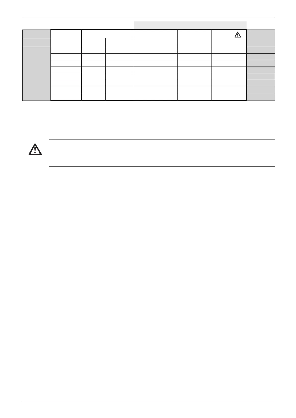
External data loggers
Device Inverter StecaGrid Vision
1)
StecaGrid Monitor Solar-Log
Web‘log
2)
Signal
Plug RJ45 RJ45 COMBICON terminal strip terminal strip RJ12
Contact
1 1 1 19 / 11 / 15 1 2 Data A
2 2 2 21 / 13 / 17 4 4 Data B
3 3 – – – – –
4 4 – – – – –
5 5 – – – – –
6 6 – – – – –
7 7 – – – – –
8 8 3 1 3 6 Ground
Tab. 8: Pin assignments of the alternative data cable
1)
Plugs for the alternative data cable are included in the scope of delivery for the StecaGrid Vision.
More information is provided in the StecaGrid Vision manual.
2)
Caution
Danger of destroying the RS485 input of the inverter.
Pin 1 of the RJ12 socket of the Web‘log data logger carries 24 V DC. Never connect the alternative
data connection cable to pin 1!
7.6.4 Termination
To prevent data transmission errors, the start and end of the RS485 bus must be terminated:
• The StecaGrid Vision (at the start of the data connection) is permanently terminated internally.
• The external data logger (at the start of the data connection) must be terminated according to
the manufacturer's specifications.
• The last inverter (at the end of the data connection) is terminated using the slide switch on the
lower side, as shown in Fig. 5, p. 47.
7.6.5 Addressing
Every inverter must be assigned its own unique address for the communication between the invert-
ers and the bus master to function correctly.
Every inverter is set with an address of 1 at the factory. This means that the addresses must be ad-
justed in systems having more than 1 inverter. The following applies:
• The address is changed at the inverter via the menu items Settings/Address.
• Only addresses ranging from 1 – 99 may be set.
• The bus master devices usually support less than 99 addresses. Consult the respective operating
instructions for these devices before setting the addresses of the inverters.
• We recommend starting with address 1 for the first inverter on the bus and then incrementing
the address by 1 for each subsequent inverter on the bus, in the same order as they are physically
installed. This makes it easier to identify the relevant inverters when their address is displayed in
messages shown on the remote display.
7.6.6 Feed-in management
Depending on the country, the grid operator must be able to reduce the effective power fed into
the grid by a photovoltaic system, depending on the power supplied by the system (e.g. applies to
Germany starting in 2012). The following products are recommended for implementing this legally
prescribed specification:
• WEB'log from Meteocontrol
• Solar-Log from Solare Datensysteme