INSTALLATION
Mounting
www.stiebel-eltron.com WPF basic | 19
9.2 Electrical installation
In accordance with VDE 0298-4, use the following cable cross-sec-
tions subject to their fuse protection:
Fuse/MCB
rating
Assignment Cable cross-section
C 16 A Compressor
(three phase)
2.5 mm²
B 16 A
Electric emergency/
booster heater (BH)
(three phase)
2.5 mm²
1.5 mm² with only two live cores and
routing on a wall or in an electrical con-
duit on a wall.
C 16 A
Compressor
WPF 5 S basic
(single phase)
1.5 mm² for open routing. Note the type
of routing!
2.5 mm² for routing through a
wall. Note the type of routing!
C 25 A
Compressor
WPF 7 S basic /
WPF 10 S basic
(single phase)
4.0 mm² for open routing. Note the type
of routing!
6.0 mm² for routing through a
wall. Note the type of routing!
C 35 A
Electric emergency/
booster heater (BH)
(single phase)
4.0 mm² when routing a multi core line
on a wall or in an electrical conduit on
a wall.
6.0 mm² for routing through a
wall. Note the type of routing!
B 16 A Control circuit fuse
(three phase)
1.5 mm²
C 16 A Control circuit fuse
(single phase)
1.5 mm²
The electrical data is given in the “Specification” chapter.
Provide separate fuses for the two power circuits of the appliance
and the control unit.
9.3 Buffer cylinder
Note
In combination with the WPF 13 basic and the WPF 16
basic, it is absolutely imperative to use a buffer cylinder.
A buffer cylinder is recommended to ensure trouble-free appliance
operation.
The buffer cylinder provides hydraulic separation of the flow rates
in the heat pump circuit and the heating circuit.
When operating without a buffer cylinder, observe the details
specified in the chapter “Minimum flow rate without buffer
cylinder”.
10. Mounting
10.1 Handling
Transport the appliance in its packaging to protect it against
damage.
Protect the appliance against heavy impact during transport.
- Only allow the appliance to be tilted during transport for a
short time to one of its longitudinal sides.
The longer the appliance is tilted, the greater the distribution
of refrigerant oil in the system.
- Storage and transport at temperatures below - 20 °C and in
excess of + 50 °C are not permissible.
10.2 Positioning
Remove the packaging film and the top and side EPS
padding.
Tilt the appliance backwards slightly and remove it from the
pallet.
Position the appliance on the prepared substrate.
Observe the minimum clearances (see chapter “Dimensions
and connection”).
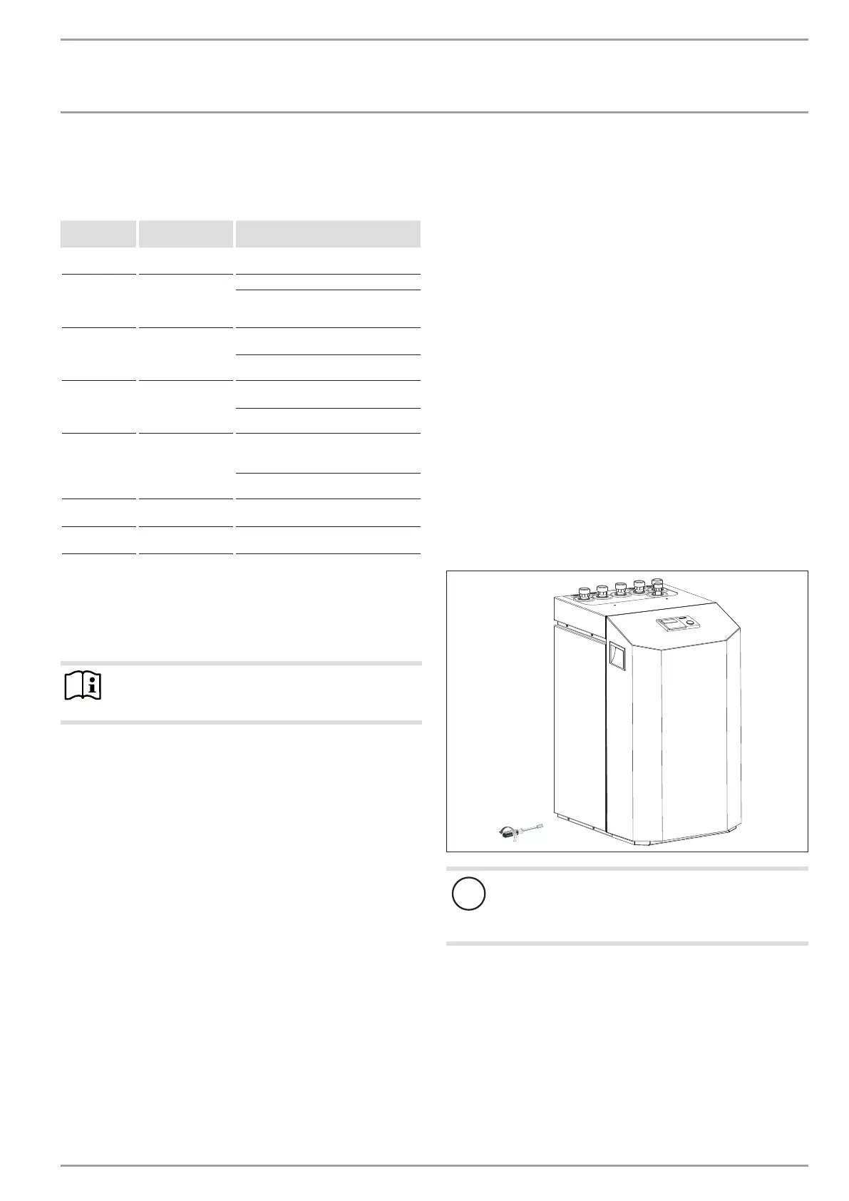
Remove the six screws from the appliance plinth, and set
down the casing onto the floor.
6x
26�03�01�1573
!
Appliance damage
The casing must stand on the floor free from the refrig-
eration unit. D. h. That means, the six plinth screws must
not be refitted.