INSTALLATION
Mounting
20 | WPF basic www.stiebel-eltron.com
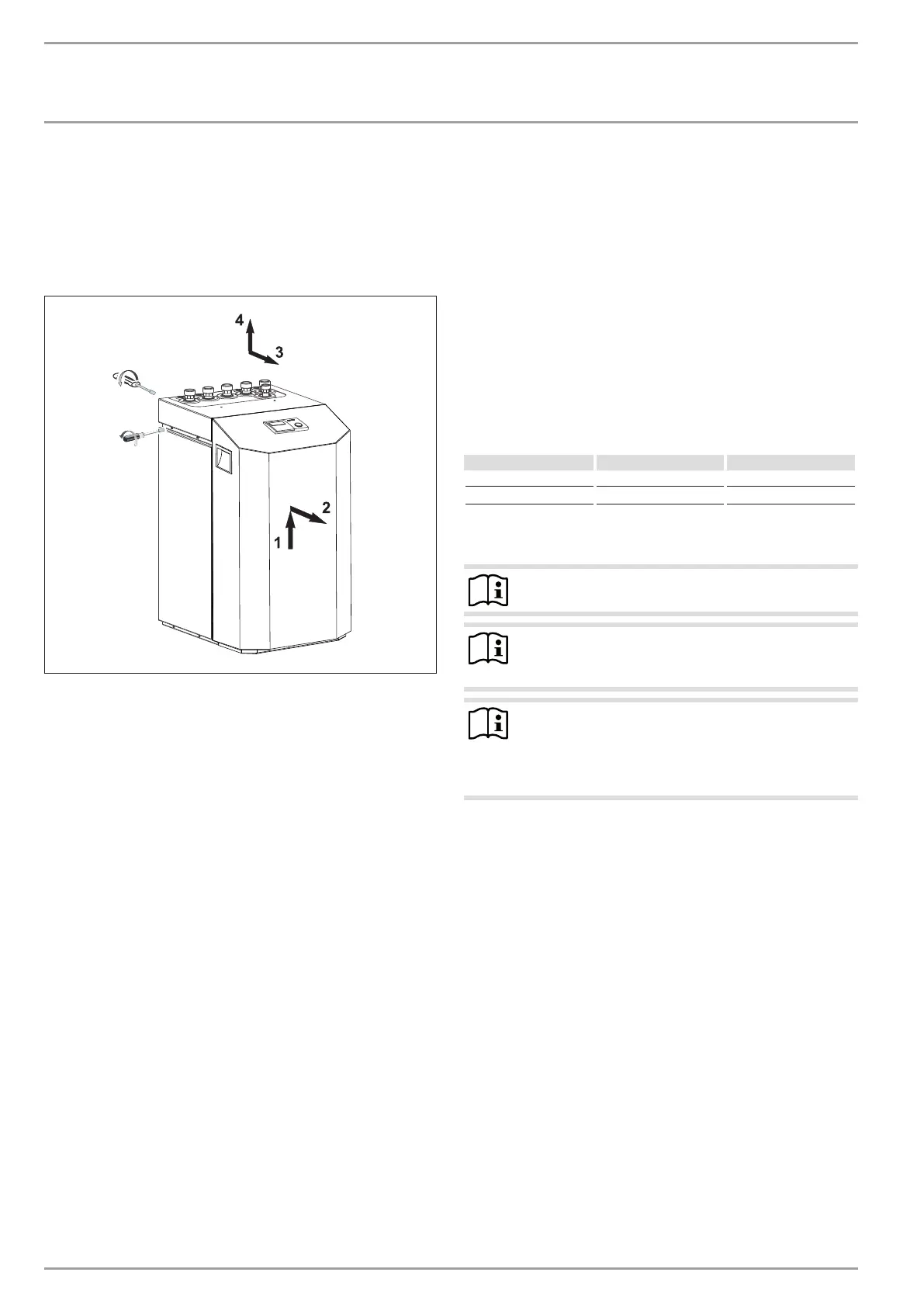
10.3 Removing the casing panels
When removing the front cover ensure, that the cables, which
connect the heat pump manager with the control panel, are not
torn off.
The same applies to the earth connection which electrically con-
nects the front cover to the casing.
2x
4x
26�03�01�1574
10.4 Installing the heat source system
Design the heat source system for the ground source heat pump
in accordance with the technical guides.
10.4.1 Permitted brine:
- Heat transfer medium as concentrate on an ethylene glycol
base, part no: 231109
- Heat transfer medium as concentrate on an ethylene glycol
base, part no: 161696
10.4.2 Circulation pump and required flow rate
Use a circulation pump with compound-filled windings to supply
the brine, to prevent an earth short circuit through condensate in
the electrical part of the pump (cold water version).
Size the circulation pump in accordance with the system-specific
conditions, h. i.e. nominal flow rate and pressure drop must be
taken into consideration (see “Specification”).
An adequate flow rate must be safeguarded at every possible
brine temperature, i.e.:
Nominal flow rate at a brine temperature of 0°C with a tolerance
of +10%.
10.4.3 Connection and filling with brine
Prior to connecting the heat pump, check the heat source circuit
for possible leaks, and flush thoroughly.
Calculate the volume of the heat source circuit. The brine volume
of the heat pump under operating conditions can be found in the
data table (see chapter “Specification”).
The overall volume is equal to the required amount of brine made
by mixing undiluted ethylene glycol and water. The chloride con-
tent of the water must not exceed 300 ppm.
Mixing ratio
The brine concentration varies when using a ground collector or
a geothermal probe as a heat source.
The mixing ratio can be found in the table below.
Ethylene glycol Water
Geothermal probe 25 % 75 %
Geothermal collector 33 % 67 %
Charging the brine circuit
Note
The WPF S series does not have a brine pressure switch.
Note
Insulate the brine lines with diffusion-proof thermal
insulation.
Note
The brine pressure switch is bridged to the power supply
utility contact at the factory.
To activate the brine pressure switch, remove the
jumper.
The brine/water heat pump is equipped with a brine pressure
switch in the brine circuit. The brine pressure switch prevents
brine getting into the ground if there is a leak in the brine circuit.
If the pressure in the brine circuit falls below 0.7bar, the brine
pressure switch turns the heat pump off. In order for the heat
pump to be enabled again, the pressure must be raised to at least
1.5bar while the heat pump is on standby.
To prevent the brine pressure switch turning the heat pump off
when there is no leak, charge the heat source side of the heat
pump during installation with a minimum pressure of >1.5bar.
Fill the system according to the following curve.