INSTALLATION
Specication
www.stiebel-eltron.com WPF basic | 67
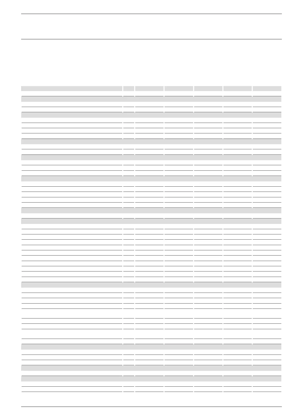
15.14 Data table WPF 5-16 basic
Output details apply to new appliances with clean heat exchangers.
The power consumption figures for the integral auxiliary drives are maximum values and may vary subject to operating point.
The power consumption of the integral auxiliary drives is included in the output details of the heat pump (to EN 14511).
WPF 5 basic WPF 7 basic WPF 10 basic WPF 13 basic WPF 16 basic
230944 230945 230946 230947 230948
Heating output
Heating output at B0/W35 (EN 14511) kW 5.88 7.64 9.7 12.59 16.64
Heating output at B10/W35 kW 7.62 9.82 12.44 16.37 20.88
Power consumption
Power consumption at B0/W35 (EN 14511) kW 1.36 1.70 2.22 2.85 4.00
Power consumption at B10/W35 kW 1.36 1.68 2.16 2.79 4.06
Max. power consumption, circulation pump on the heating side W 70 70 70 70 70
Power consumption, emergency/booster heater kW 8.8 8.8 8.8 8.8 8.8
Coefficient of performance
COP at B0/W35 (EN 14511) 4.33 4.50 4.37 4.42 4.16
Coefficient of performance at B10/W35 5.60 5.85 5.76 5.87 5.14
Sound emissions
Sound power level (EN 12102) dB(A) 46 47 51 53 53
Sound pressure level at a distance of 1m in a free field dB(A) 38 39 43 45 45
Sound pressure level at a distance of 5m in a free field dB(A) 24 25 29 31 31
Application limits
Max. permissible pressure MPa 0.3 0.3 0.3 0.3 0.3
Min. application limit on the heating side °C 15 15 15 15 15
Max. application limit on the heating side °C 60 60 60 60 60
Min. application limit, heat source °C -5 -5 -5 -5 -5
Max. application limit, heat source °C 20 20 20 20 20
Energy data
Energy efficiency class A+/A++ A+/A++ A+/A++ A+/A++ A+/A++
Electrical data
Frequency Hz 50 50 50 50 50
Control unit fuse/MCB A 1 x B 16 1 x B 16 1 x B 16 1 x B 16 1 x B 16
Compressor fuse/MCB A 3 x C 16 3 x C 16 3 x C 16 3 x C 16 3 x C 16
MCB/fuse protection, emergency/booster heater A 3 x B 16 3 x B 16 3 x B 16 3 x B 16 3 x B 16
Rated voltage, control unit V 230 230 230 230 230
Rated voltage, compressor V 400 400 400 400 400
Rated voltage, emergency/booster heater V 400 400 400 400 400
Control unit phases 1/N/PE 1/N/PE 1/N/PE 1/N/PE 1/N/PE
Compressor phases 3/N/PE 3/N/PE 3/N/PE 3/N/PE 3/N/PE
Emergency/booster heater phases 3/N/PE 3/N/PE 3/N/PE 3/N/PE 3/N/PE
Starting current (with/without starting current limiter) A 26/- 30/- 27/- 28/- 29/-
Versions
Refrigerant R410 A R410 A R410 A R410 A R410 A
Refrigerant charge kg 1.73 2 2.6 2.5 2.6
CO
2
equivalent (CO
2
e) t 3.61 4.18 5.43 5.22 5.22
Global warming potential of the refrigerant (GWP100) 2088 2088 2088 2088 2088
Compressor oil Emkarate RL 32
3MAF
Emkarate RL 32
3MAF
Emkarate RL 32
3MAF
Emkarate RL 32
3MAF
Emkarate RL 32
3MAF
Evaporator material 1.4401/Cu 1.4401/Cu 1.4401/Cu 1.4401/Cu 1.4401/Cu
Condenser material 1.4401/Cu 1.4401/Cu 1.4401/Cu 1.4401/Cu 1.4401/Cu
Circulation pump type on the heating side Stratos PARA
25/1-7
Stratos PARA
25/1-7
Stratos PARA
25/1-7
Stratos PARA
25/1-7
Stratos PARA
25/1-7
IP rating IP20 IP20 IP20 IP20 IP20
Dimensions
Height mm 960 960 960 960 960
Width mm 510 510 510 510 510
Depth mm 680 680 680 680 680
Weight
Weight kg 107 113 120 128 131
Connections
Connection on the heating side G 1 1/4 G 1 1/4 G 1 1/4 G 1 1/4 G 1 1/4
Connection on the heat source side G 1 1/4 G 1 1/4 G 1 1/4 G 1 1/4 G 1 1/4