INSTALLATION
Troubleshooting
www.stiebel-eltron.com WPF basic | 43
13. Troubleshooting
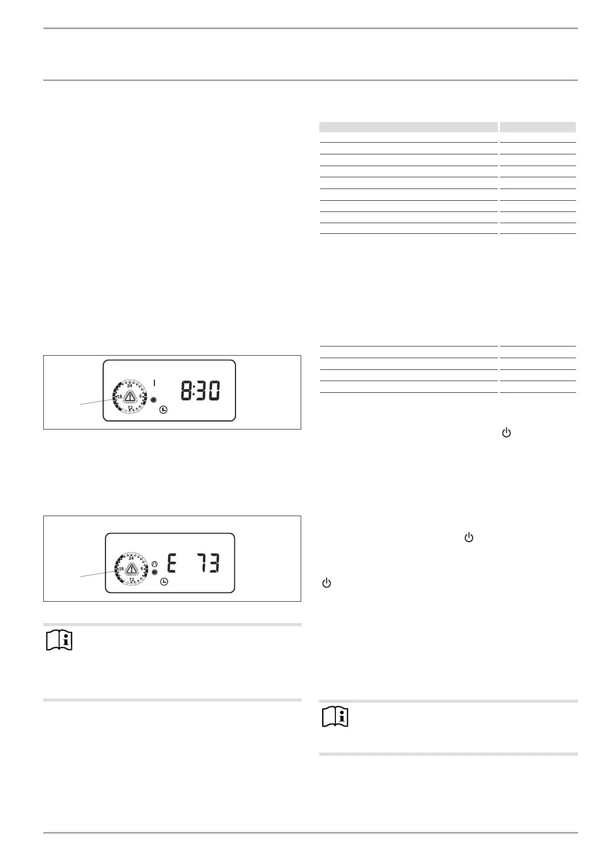
13.1 Fault display
Faults/errors in the system or in the heat pump are indicated on
the display. All parameters required for an in-depth system analy-
sis can be checked under the system menu items COMMISSIONING
and TEMPERATURES. For troubleshooting, analyse all available
parameters before opening the heat pump control panel.
The controller will not indicate that the booster heater high limit
safety cut-out has responded. The high limit safety cut-out can be
reset by your contractor through pressing the reset button. The
high limit safety cut-out response is generally caused by air in the
heating circuit or an inadequate heating flow rate.
Check the heating flow rate and ventilate the heating system.
13.1.1 Heat pump-specific or hardware faults
All faults are displayed.
Example: High pressure fault
26�03�01�1063
1
HP SENSOR MAX
1 Fault message (flashing)
All faults cause the heat pump to shut down. The idle period will
be set and, with the exception of MAX HOT GAS T, ALl faults are
written to the fault list.
13.1.2 Sensor break = sensor fault
26�03�01�1064
1
SENSOR BROKEN
1 Fault message (flashing)
Note
This fault code refers to temperature sensors that can be
called up under the parameter TEMPERATURES. These
faults are not entered into the fault list. The system will
not be shut down. The display message will extinguish
immediately after the fault has been removed.
Observe the list under system parameter TEMPERATURES.
Sensor Fault code
Outside temperature E 75
Remote control E 80
Actual DHW temperature E 76
Actual heat pump return temperature (H1) E 73
Actual mixer flow temperature (H2) E 70
Actual heat pump flow temperature E 72
Actual source flow temperature E 71
High pressure sensor E 130
LP sensor E 128
13.1.3 Fault message with DCO enabled
In connection with the dial-up connection controller DCO enabled,
the sensor faults listed above result in the transmission of the error
codes (E75 to E130) by SMS to the authorised recipient.
In addition, the following fault codes are transmitted as text mes-
sage:
Contactor stuck E 20
No power E 21
Low pressure E 22
HIGH PRESSURE E 23
HP sensor max E 24
13.1.4 Checking brine pressure
Check brine pressure if the heat pump is blocked for more
than three hours (standby symbol flashes [
]).
Check the brine pipe for leaks.
Remedy any leaks.
Recharge the system (see chapter “Installation/ Installation/
Installing the heat source system/ Connection and brine
charging/ Charging the brine circuit”).
13.1.5 The heat pump does not run
The heat pump is in standby mode [
]
Remedy: Change to automatic mode
The power supply has been blocked; the standby symbol flashes
[
]
Remedy: Wait; the heat pump restarts automatically at the end
of the blocking time.
There is no heat demand
Remedy: System parameter TEMPERATURES, check temperatures
and compare the actual and set temperatures.
Possibly incorrect fuse rating
Remedy: See Specification
Note
Under these circumstances, you can only restart the heat
pump after the fault has been removed and the heat
pump has been reset (parameter WPM RESET).
Additional parameters available for system analysis:
Quick start:
Check the heat pump compressor by implementing a quick start